0000029661 00000 n
The Honeywell UDC 3500 Universal Digital Controller is Honeywells top end controller in the UDC series. How does adding a 250-ohm resistor make HART work? 0000029733 00000 n Automation & Control Components
These cookies will be stored in your browser only with your consent. (PROGRAM1, PROGRAM2, etc.).  15 27
0000002442 00000 n
15 27
0000002442 00000 n
 0000031928 00000 n
0000002610 00000 n
0000031928 00000 n
0000002610 00000 n
 0000028957 00000 n
(Terms DAP to Delivery Address)
(LogOut/ 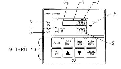 Kalsdorfer Strae 26 a8073 Feldkirchen bei Grazsterreich, Tel: +43 316 40 33 01Mail: office@sensorwell.at, Aisttalstrae 34311 Schwertbergsterreich, Tel: +43 7262 61700Mail: office@sensorwell.at, T: +43 316 40 33 01M: office@sensorwell.at. 0000033813 00000 n
0000002326 00000 n 0000024170 00000 n 0000033517 00000 n if ($(this).prop('checked')) { (i.e. Pressure, Website developed by Partnered Solutions IT, Designed by Ruby Porter Marketing & Design, 3 Universal Analog Inputs (can be configured to operate as 1 Universal and 4 High Level Inputs), Infrared PC & Pocket PC configuration. 0000003060 00000 n Warrington u Theres no Program Select button on the keypad. 0000033157 00000 n xref DC3500-EE-0000-160-00000-E0-0, Manufacturer: Honeywell Process Solution (PMC) 0 You are here: Home
* Your assessment is very important for improving the workof artificial intelligence, which forms the content of this project. 0000029150 00000 n Automation Control endstream endobj 517 0 obj <>stream Please call either office for more information: Monitor and control temperatures, pressures and levels in various applications. 0000001579 00000 n 0000002580 00000 n 0000002874 00000 n xref Its universal spare parts further add to the ease of maintenance. xref These cookies do not store any personal information. When these are combined with the Accutune III tuning with fuzzy logic overshoot suppression, the result is price/performance leadership. Change), You are commenting using your Facebook account. 0000008355 00000 n 0000007039 00000 n 0000030548 00000 n
Copyright 1995-2022 eBay Inc. Todos os direitos reservados. 15 0 obj <> endobj 0000019714 00000 n 0000031768 00000 n Cookies erleichtern die Bereitstellung unseres Angebots. 0000031337 00000 n Honeywell Process Solution (PMC) 0000003472 00000 n 0000009236 00000 n 41 0 obj <>stream 0000052539 00000 n Se usar a opo Comprar j!, voc comprar apenas este item. 0000002838 00000 n Process Controllers & Programmers Please contact either office for more information (Glasgow 0141 641 5920 or Warrington 01925 572401). trailer 4059 0 obj <> endobj HONEYWELL UDC3500 PRODUCT MANUAL UNI. xb```b`` ,l@q>uFl/k8(E5bTQyAmO 0000054196 00000 n 0000003368 00000 n We also use third-party cookies that help us analyze and understand how you use this website. Greyed out shipping options indicate services not available, as the certain criteria has not been met. It is available as a single- or dual-loop controller and can be used in wash-down applications. The universal digital controller possesses adequate power and cost effectively brings with it several advanced features such as enhanced set point programming, fast scanning and on-board diagnostics. Kempston Controls LLC is a UK electrical and electronic components distributor, providing fuses, sensors, control components, industrial automation equipment and more. All shipping options below are for UK shipping only. (259 kb). $(this).prop('checked', true); You also have the option to opt-out of these cookies. 2]0sv $V:GdVg/u@KlD6jBaHCgA%Lh\ 7 Aa/o7%EB|FeXr%vYd~kAb0JL4%U5YigKG[F 4(! l"H,4l,l7nA(cakqApEH- d'T,@;K?c 7 *B] (Qa"*Ld,:` :LVd(00?V {2@ \ 0000001584 00000 n Comprehensive data acquisition system for process measurement, logging and control. 0000004979 00000 n 0000000979 00000 n 0000019469 00000 n It scrolls through a list of items in the lower display, eventually showing PROGRAMX, which, when you change with the up and down arrow keys, lets you scroll through and select one of your stored setpoint programs. x]O@?-=I3 wi)?tW@'93oQ2~zy?jW?~CZ}_\~t>_s;skv#OpCn5Y 0000049867 00000 n endstream endobj 512 0 obj <>/Outlines 520 0 R/PageMode/UseOutlines/Pages 505 0 R/Type/Catalog>> endobj 513 0 obj <>/MediaBox[0 0 594.75 841.5]/Parent 506 0 R/Resources<>/ProcSet[/PDF/Text]>>/Rotate 0/Type/Page>> endobj 514 0 obj <>stream Cheshire, WA2 8TX %PDF-1.4 % %PDF-1.3 % $(this).parent().find('button[type="submit"]').click(); 0000010185 00000 n %%EOF PDF Product Datasheet for DC3500-EE-0000-160-00000-E0-0 0000030281 00000 n
from AED 197.50 BNZ R37`M @QH5@0b(h@(jxb13# 9L4d~[&o X]":ea=6 Gl010>z rL6vp08 3 pL'|@ EEH 0000001864 00000 n <<5FCDCF32DF671A4FA55E4114271D4BF1>]>> 0000030390 00000 n Manufacturers 0000019306 00000 n Wiring industrial thermocouples: Basic tips and suggestions. But opting out of some of these cookies may affect your browsing experience. 0000001893 00000 n }); Its universal spare parts further add to the ease of maintenance. its after the cut off time or items in your basket are not in stock for Next Day, Express or Saturday delivery). Multiple Analog Inputs can be configured as follows. Change), You are commenting using your Twitter account. We'll assume you're ok with this, but you can opt-out if you wish. 0000003746 00000 n UDC3500 Universal Digital Controller is a DIN controller available as a single- or dual-loop controller with advanced features such as enhanced set point programming, fast scanning and on-board diagnostics and a scanning rate of 166ms. Users benefit from an accuracy of 0.10% and a scanning rate of 166ms. No garantimos a exatido nem a clareza da traduo resultante. 0000003329 00000 n But after configuring all four profiles, I was stuck on how to select the one I wanted the controller to use. UAE 0000032507 00000 n You can follow any responses to this entry through RSS 2.0. WDJ Oferecemos esta ferramenta de traduo apenas para lhe proporcionar maior convenincia. International Priority to United Arab Emirates 0000003218 00000 n ^J]/t}Q.
0000001383 00000 n 0000006638 00000 n Observao: No garantimos a exatido da traduo resultante, nem o acesso mesma. 0 0000000016 00000 n Ive been working with Honeywell controllers for 25 years now, and I have a pretty solid feel for how the manuals are laid out (and yes, Ive read them): Specs, mounting, wiring, configuration, more configuration, even more configuration, and then a chapter on operations. The UDC 3500 universal controller can be configured with a pocket PC or computer and is very easy to operate and maintain. 0000033324 00000 n Our technical team can help find an alternative! 0000000016 00000 n Real-world insights into process measurement and analytical applications, technology, and instrumentation, View UCw52-WO6SMNWHMrx1A3uL6ws profile on YouTube, Solving installation problems for radar tank leveltransmitters, Making a Siemens clamp-on flowmeter setup record easy toread, latest Honeywell UDC3500 controller operations manual, Lesman Instrument Company is the authorized Honeywell stocking distributor. 0000003395 00000 n Dubai, Atualize a janela do navegador e tente novamente. 0 So I was mystified on how I was going to select my setpoint profile program #3. The Sensorwell team has been working as a competent and reliable trading partner in the field of sensors, automation and security technology since 2005. Easily Field Up-gradeable Modular Design. p%+k"\\Q6pXRB5lX, p+%Uf%Uf%Uf 2c(2c(2c\=4Uf5\el p\ p 5vBZ5fQh 0000032978 00000 n 0000000016 00000 n 0000015268 00000 n Honeywells UDC 3500 DIN Controllers address these requirements simply and effectively. 0000029689 00000 n 0000001085 00000 n 0000042805 00000 n 0000012124 00000 n 0000010593 00000 n x |E\U]}NL}"HH& h WF}x" J"eq8(`o8{v. { 0000054371 00000 n x * 7rhjp#nU5nF^Up#W1z94F7FFM)MlqX-ZLl&68bbs#=o=Vc[,},}Oq^4p $('#wso_slider_search').click(function(){ 0000013662 00000 n 0000031538 00000 n Batch Control, digital controller, honeywell controller, Honeywell controllers, honeywell udc, process loop controller, ramp soak programmer, setpoint, setpoint profile, UDC3500 configuration. 1702 28th St. This website uses cookies to improve your experience. Fill in the below to get started. Springfield, OR 97477 0000001136 00000 n O vendedor assume toda a responsabilidade pelo anncio. 0000033381 00000 n
endstream endobj 4090 0 obj <>/Size 4059/Type/XRef>>stream x1 04s\GMyC. Only logged in customers who have purchased this product may leave a review. }); UDC3500 Universal Digital Controller Product Manual. trailer startxref You can leave a response, or trackback from your own site. United Kingdom. HWr6}WL; a IN'xPK=. Necessary cookies are absolutely essential for the website to function properly. Change). Copyright 2022 Kempston Controls LLC . This category only includes cookies that ensures basic functionalities and security features of the website. (LogOut/
The Honeywell UDC3500 digital controller can support up to four setpoint programs, the ramp/soak profiles used in batch control operations. The UDC3500 offers a top end accuracy of 0.10% and a scanning rate of 166ms. Email: sales@kempstoncontrols.ae. 0000052730 00000 n 0000032679 00000 n 0000033142 00000 n 4059 33 0000031187 00000 n Se quiser comprar os itens adicionais que voc selecionou para poder receber esta oferta. 0000030117 00000 n } For our overseas customers, we offer a very competitive and fast delivery service; however, if you prefer to collect using your own courier, then we can also arrange that at no extra cost. 0000030815 00000 n 0000004944 00000 n 0000032833 00000 n document.getElementById( "ak_js_1" ).setAttribute( "value", ( new Date() ).getTime() ); Want to learn all the stuff they left out of technology classes or forgot to put in the instrument manuals? 0000000836 00000 n
4091 0 obj <>stream Ainda no h nenhuma avaliao ou resenha, Preo de vendas recentes fornecido pelo vendedor, Adicione ao carrinho para salvar com esta oferta especial. startxref But I still couldnt find anything about selecting a program.
Fill in your details below or click an icon to log in: You are commenting using your WordPress.com account. <]>> trailer Copyright 2022 Cascade Automation Inc. Honeywell UDC3500 Universal Digital Controller, New Surplus Transmitters - Diff. 0000003422 00000 n Help us better your experience! Ocorreu um problema. Outros Equipamentos Comerciais e Industriais. 0000032111 00000 n Process logic controller with modular design to meet automation needs. Ourinstrumentation engineers are product trained and able to help with instrument selection within the full Honeywell Field Product instrumentation portfolio including the entire Universal Digital Controller family, which incorporates not only the UDC3500 but the more economically specd UDC1200, UDC1700 and UDC2500. Fluidic order directly with the Honeywell factory via an exclusive channel partner web portal and hold stock for some common lines. endstream endobj 515 0 obj <> endobj 516 0 obj <>stream Visit Lesman.com for the latest Honeywell UDC3500 controller operations manual. Telephone: +971 (0) 4 2987111 UNIVERSAL DIGITAL CONTROLLER, UDC3500, ELECTRO MECHANICAL RELAY, ENGLISH MANUAL (HARD COPY), PDF Product Datasheet for DC3500-EE-0000-160-00000-E0-0, UK standard delivery, usually 1 - 2 days (1 per day, minimum order AED 20.00), UK standard delivery, usually within 1 - 2 days, Collection is available from our site - please call if your order is urgent. 552 0 obj <>stream (259 kb). endstream endobj 16 0 obj <> endobj 17 0 obj <> endobj 18 0 obj <>/ColorSpace<>/Font<>/ProcSet[/PDF/Text/ImageC]/ExtGState<>/Pattern<>>> endobj 19 0 obj <> endobj 20 0 obj <> endobj 21 0 obj <> endobj 22 0 obj <> endobj 23 0 obj <> endobj 24 0 obj <>stream The UDC3500 Universal Digital Controller packs new powerful features in the popular 1/4 DIN size. Fluidic hold an exclusive channel partner agreement with Honeywell Field Products division. Manualzz provides technical documentation library and question & answer platform.Its a community-based project which helps to repair anything. Glasgow, G32 8EY Subscribe to my blog, and whenever I add a post, you'll get an e-mail notification. 511 0 obj <> endobj 0000001728 00000 n
UNIVERSAL DIGITAL CONTROLLER, UDC3500, ELECTRO MECHANICAL RELAY, ENGLISH MANUAL (HARD COPY), PDF Product Datasheet for DC3500-EE-0000-160-00000-E0-0 xb```]eaXD C{X%p[Q$AK I{WVF^Rev38hfg`2-@0?H3-10@| This entry was posted on September 11, 2014, 10:11 am and is filed under Batch Control, Configuration, Control, Honeywell, Loop Controllers. Umm Ramool, 0000002034 00000 n If you are located outside that area, you can find your local sales office or get technical assistance by visiting Honeywells contact page. ? 0000001203 00000 n Let us know what country you are in. United Kingdom, CG2 Warrington Business Park (LogOut/ It is mandatory to procure user consent prior to running these cookies on your website. === The universal digital controller possesses adequate power and cost effectively brings with it several advanced features such as enhanced set point programming, fast scanning and on-board diagnostics. Manufacturered to a DIN size, the UDC3500 is available as a single- or dual-loop controller and can be used in wash-down IP66 applications. Delivery prices below are Exc VAT. 511 42 UDC3200 Manual - Jackson Oven Supply, Inc. DR4500A Classic Series Circular Chart Recorder With or Without, DR4500A Truline Circular Chart Recorder With or Without Control, Series DR4300 Digital Circular Chart Recorders, DC330B Manual del usuario - Honeywell Process Solutions. This website uses cookies to improve your experience while you navigate through the website. 0000003976 00000 n
0000033933 00000 n UDC 3500 is a next-generation universal controller in the popular DIN size. * Delivery services are subject to exception areas, click exceptions to view the affected areas or use the shipping estimator tool to view delivery options. 0000033633 00000 n %%EOF <<650BD5912763A84DBFC1E38787881012>]/Prev 334818>> 0000033642 00000 n Mit der Nutzung unserer Seite erklren Sie sich damit einverstanden, dass wir Cookies verwenden. A large part of the team consists of former Honeywell employees with many years of experience in the industry. PO Box: 60998, Veja detalhes no carrinho. USA. 0000030924 00000 n $('[name="fwp_productcat"]').change(function(){ 0000036347 00000 n This field is for validation purposes and should be left unchanged. 0000010969 00000 n Manufacturing processes need tailor-made and effective process control tools, for monitoring and controlling process variables, at low prices to optimize their operations. 0000032364 00000 n Unmatched application power includes: Infrared (IR) Configuration interface, three universal analog inputs, two loops of control and two Math Algorithms. Out of these, the cookies that are categorized as necessary are stored on your browser as they are essential for the working of basic functionalities of the website. Universal digital limit controller (120 pages), Honeywell universal digital controller product manual (243 pages), Manual will be automatically added to "My Manuals", Figure 1-2 Screen Capture of Process Instrument Explorer Running on a Pocket PC, Figure 1-3 Depiction of Infrared Communications, Figure 2-11 Optional Analog Input Jumper Positions, Control and Alarm Relay Contact Information, Table 2-2 Control Relay Contact Information, Table 2-3 Alarm Relay Contact Information, Figure 2-2 Mounting Dimensions (Not to Scale), Table 2-6 Single or Cascade Loop Controller - Loop 1 Output Functionality and Restrictions, Table 2-7 Dual Loop Controller - Loop 2 Output Functionality and Restrictions, Figure 2-9 HLAI Inputs 2 and 4 Connections, Figure 2-10 HLAI Inputs 3 and 5 Connections, Figure 2-14 Output #2 - Electromechanical Relay Output, Figure 2-15 Output #2 - Solid State Relay Output, Figure 2-16 Output #2 - Open Collector Output- Third, Figure 2-17 Output #2 - Third Current Output, Figure 2-18 Output #2 - Dual Relay Output for Time Duplex, Figure 2-19 Output #2 - Dual Relay Output for Position Proportional or Three Position Step Control, Figure 2-20 RS-422/485 Communications Option Connections, Figure 2-21 Ethernet Communications Option with Adaptor Board, Table 2-8 Terminals for Connecting a UDC to a MDI Compliant Hub or Switch Utilizing a Cross-Over Cable, Figure 2-22 Ethernet Communications Option Without Adaptor Board, Table 2-9 Terminals for Connecting a UDC Directly to a PC Utilizing a Straight-Through Cable, Figure 2-24 Optional Electromechanical Relay Outputs, Figure 2-25 Transmitter Power for 4-20 Ma - 2 Wire Transmitter Using Open Collector Output, Figure 2-26 Transmitter Power for 4-20 Ma - 2 Wire Transmitter Using Second Current Output, Table 3-5 TUNING 2 Group Function Prompts, Table 3-7 ACCUTUNE Group Function Prompts, Table 3-8 ALGORTHM Group Function Prompts, Figure 3-2 Example of Eight Segment Characterizer, Table 3-12 INPUT 1 Group Function Prompts, Table 3-13 INPUT 2 Group Function Prompts, Table 3-14 INPUT 3 Group Function Prompts, Table 3-15 INPUT 4 Group Function Prompts, Table 3-16 INPUT 5 Group Function Prompts, Table 3-17 CONTROL Group Function Prompts, Table 3-18 CONTROL2 Group Function Prompts, Table 3-20 Communications Group Function Prompts, Table 3-23 MAINTENANCE Group Function Prompts, Table 3-24 DISPLAY Group Function Prompts, Table 3-25 READ MAINTENANCE Group Function Prompts, Table 3-26 TIME EVT Group Function Prompts, Tool Ethernet and Email Configuration Screens, 4 Monitoring and Operating the Controller, Table 4-1 Procedure to Enter a Security Code, Table 4-3 Lower Display Key Parameter Prompts, Table 4-4 Procedure for Starting up the Controller, Table 4-7 Procedure for Changing the Local Setpoints, Table 4-8 Procedure for Switching between Setpoints, Table 4-10 Procedure for Using AUTOMATIC TUNE at Start-Up for Duplex Control, Using AUTOMATIC TUNE at Start-Up for Duplex (Heat/Cool), Table 4-11 Procedure for Using BLENDED TUNE at Start-Up for Duplex Control, Using BLENDED TUNE at Start-Up for Duplex (Heat/Cool), Table 4-12 Procedure for Using MANUAL TUNE for Heat Side of Duplex Control, Table 4-13 Procedure for Using MANUAL TUNE for Cool Side of Duplex Control, Using MANUAL TUNE at Start-Up for Duplex (Heat/Cool), Table 4-14 Procedure for Accessing Accutune Error Codes, Table 4-17 Procedure for Switching PID SETS from the Keyboard, Table 4-18 Logic Gates Constraints and Dynamic Operation Status, Table 4-19 Digital Input Option Action on Contact Closure, Table 4-20 Digital Input Combinations "DIG IN1" or "DIG IN2, Table 4-21 Digital Inputs 1 and 2 Combination, Table 4-22 Auto/Manual Station Mode Configuration Procedure, Figure 4-3 Functional Overview Block Diagram of a Single Loop (Loop #1) or Dual Loop Controller (Loop #1 and Loop #2), Figure 4-4 Functional Overview Block Diagram of Internal Cascade Controller, Table 4-23 Procedure for Selecting Two Loop Algorithm, Table 4-24 Digital Display Indication-Two Loops, Table 4-25 Procedure for Displaying Alarm Setpoints, Table 4-26 Procedure for Displaying TPSC Motor Position, Setting a Failsafe Output Value for Restart after a Power Loss, Table 4-27 Procedure for Setting a Failsafe Value, Carbon Potential, Oxygen and Dewpoint Algorithms, Table 4-28 Procedure for Setting a Failsafe Mode, Figure 4-10 Alarm Details Maintenance Screen, Figure 4-11 Status Data Maintenance Screen, Figure 4-12 Diagnostic History Maintenance Screen, Figure 4-13 Ethernet Status Maintenance Screen, Figure 4-14 Healthwatch Data Maintenance Screen, Figure 4-15 Healthwatch Data Reset Screen, Figure 4-17 Real Time Clock Maintenance Screen, Figure 4-19 Configuration Upload in Progress, Figure 4-20 Ethernet Communications Address, Figure 4-21 Configuration Upload in Progress, Table 5-1 Voltage, Milliamp and Resistance Equivalents for Input Range Values, Table 5-3 Set up Wiring Procedure for Thermocouple Inputs Using an Ice Bath, Figure 5-2 Wiring Connections for Thermocouple Inputs Using an Ice Bath, Thermocouple Inputs Using a Thermocouple Source, Table 5-4 Set up Wiring Procedure for Thermocouple Inputs Using a Thermocouple Source, Figure 5-3 Wiring Connections for Thermocouple Inputs Using a Thermocouple Source, Table 5-5 Set up Wiring Procedure for RTD Inputs, Figure 5-4 Wiring Connections for RTD (Resistance Thermometer Device), Radiamatic, Millivolts, Volts, Carbon, Oxygen or Thermocouple Differential Inputs, Table 5-6 Set up Wiring Procedure for Radiamatic, Millivolts, Volts, Carbon, Oxygen or Thermocouple Differential Inputs (Except 0-10 Volts and -1 to 1 Volts), Figure 5-5 Wiring Connections for Radiamatic, Millivolts, Volts, Carbon, Oxygen or Thermocouple Differential, Table 5-7 Procedure to Determine Calibration Voltages for Thermocouple Differential Input Types Other than the Factory Setting, Table 5-8 Set up Wiring Procedure for 0 to 10 Volts or -1 to 1 Volts, Figure 5-6 Wiring Connections for 0 to 10 Volts or -1 to 1 Volts, Table 5-9 Set up Wiring Procedure for Milliampere Inputs, Figure 5-7 Wiring Connections for Milliampere Inputs, Table 5-10 Set up Wiring Procedure for Dual High Level Voltage Inputs, Figure 5-8 Wiring Connections for Dual High Level Voltage Inputs, Table 5-11 Set up Wiring Procedure for Dual High Level Milliampere Inputs, Figure 5-9 Wiring Connections for Dual High Level Milliampere Inputs, Table 6-1 Set up Wiring Procedure for the First Current Output, Figure 6-1 Wiring Connections for Calibrating the First Current Output, Table 6-2 First Current Output Calibration Procedure, Table 6-3 Set up Wiring Procedure for the Second Current Output, Figure 6-2 Wiring Connections for Calibrating the Second Current Output, Table 6-4 Second Current Output Calibration Procedure, Table 6-5 Set up Wiring Procedure for the Third Current Output, Figure 6-3 Wiring Connections for Calibrating Third Current Output, Table 6-6 Third Current Output Calibration Procedure, Position Proportional and Three Position Step Output Calibration, Table 6-7 Position Proportional and Three Position Step Output Calibration Procedure, Table 7-1 Procedure for Identifying the Software Version, Table 7-2 Procedure for Displaying the Status Test Results, Table 7-5 Troubleshooting Power Failure Symptoms, Table 7-6 Troubleshooting Current Output Failure, Table 7-7 Troubleshooting Position Proportional Output Failure, Table 7-8 Troubleshooting Time Proportional Output Failure, Procedure #5 - Current/Time or Time Current/Proportional, Table 7-9 Troubleshooting Current/Time or Time/Current Proportional Output Failure, Table 7-10 Troubleshooting Alarm Relay Output Failure, Table 7-11 Troubleshooting a Keyboard Failure, Table 7-12 Troubleshooting an Analog Input Failure, Table 7-13 Troubleshooting a RS-485 Communications Failure, Table 7-14 Troubleshooting an Ethernet Communications Failure, Table 7-15 Troubleshooting an Email Failure, Table 7-16 Restoring Factory Configuration, Controller Honeywell UDC3500 Quick Start Manual, Controller Honeywell UDC3300 Product Manual, Controller Honeywell UDC3300 Instruction Manual, Controller Honeywell UDC 3300 Product Manual, Controller Honeywell UDC3200 Product Manual, Controller Honeywell UDC3200 series Operator's Manual, Controller Honeywell UDC2500 Product Manual, Controller Honeywell UDC 6300 Product Manual, Controller Honeywell UDC 1000 Micro-Pro Product Manual, Page 22: Process Instrument Explorer Software, Page 23: Figure 1-3 Depiction Of Infrared Communications, Page 32: Figure 2-1 Model Number Interpretation, Page 33: Control And Alarm Relay Contact Information, Page 37: Table 2-5 Permissible Wiring Bundling, Page 39: Table 2-6 Single Or Cascade Loop Controller - Loop 1 Output Functionality And Restrictions, Page 40: Table 2-7 Dual Loop Controller - Loop 2 Output Functionality And Restrictions, Page 46: Figure 2-9 Hlai Inputs 2 And 4 Connections, Page 47: Figure 2-10 Hlai Inputs 3 And 5 Connections, Page 49: Figure 2-14 Output #2 - Electromechanical Relay Output, Page 50: Figure 2-16 Output #2 - Open Collector Output- Third, Page 51: Figure 2-18 Output #2 - Dual Relay Output For Time Duplex, Page 52: Figure 2-20 Rs-422/485 Communications Option Connections, Page 53: Table 2-8 Terminals For Connecting A Udc To A Mdi Compliant Hub Or Switch Utilizing A Cross-Over Cable, Page 54: Table 2-9 Terminals For Connecting A Udc Directly To A Pc Utilizing A Straight-Through Cable, Page 55: Figure 2-24 Optional Electromechanical Relay Outputs, Page 56: Figure 2-26 Transmitter Power For 4-20 Ma - 2 Wire Transmitter Using Second Current Output, Page 77: Table 3-7 Accutune Group Function Prompts, Page 102: Figure 3-2 Example Of Eight Segment Characterizer, Page 169: Table 3-21 Alarms Group Function Prompts, Page 185: Tool Ethernet And Email Configuration Screens, Page 186: Figure 3-4 Email Configuration Screen, Page 195: Monitoring And Operating The Controller, Page 200: Viewing The Operating Parameters, Page 202: Start Up Procedure For Operation, Page 204: What Happens When You Change Modes, Page 205: Table 4-7 Procedure For Changing The Local Setpoints, Page 211: Using Automatic Tune At Start-Up For Duplex (Heat/Cool), Page 212: Using Blended Tune At Start-Up For Duplex (Heat/Cool), Page 213: Using Manual Tune At Start-Up For Duplex (Heat/Cool), Page 216: Using Two Sets Of Tuning Constants, Page 217: Table 4-17 Procedure For Switching Pid Sets From The Keyboard, Page 222: Digital Input Option (Remote Switching), Page 225: Table 4-20 Digital Input Combinations "Dig In1" Or "Dig In2, Page 226: Table 4-21 Digital Inputs 1 And 2 Combination, Page 228: Table 4-22 Auto/Manual Station Mode Configuration Procedure, Page 232: Figure 4-3 Functional Overview Block Diagram Of A Single Loop (Loop #1) Or Dual Loop Controller (Loop #1 And Loop #2), Page 233: Figure 4-4 Functional Overview Block Diagram Of Internal Cascade Controller, Page 234: Configuring Two Loops Of Control, Page 235: Monitoring Two Loops Of Control, Page 237: Table 4-25 Procedure For Displaying Alarm Setpoints, Page 238: Setpoint Programming Event Alarms, Page 239: Three Position Step Control Algorithm, Page 240: Setting A Failsafe Output Value For Restart After A Power Loss, Page 243: Figure 4-6 Carbon Potential Control, Page 246: Table 4-29 Running A Setpoint Ramp, Page 251: Figure 4-7 Ramp/Soak Profile Example, Page 252: Figure 4-8 Program Record Sheet, Page 254: Table 4-31 Run/Monitor Functions, Page 257: Figure 4-10 Alarm Details Maintenance Screen, Page 258: Loop Data Digital Input Details, Page 259: Figure 4-11 Status Data Maintenance Screen, Page 260: Figure 4-12 Diagnostic History Maintenance Screen, Page 261: Figure 4-13 Ethernet Status Maintenance Screen, Page 262: Figure 4-14 Healthwatch Data Maintenance Screen, Page 263: Figure 4-15 Healthwatch Data Reset Screen, Page 264: Figure 4-16 Totalizer Maintenance Screen, Page 265: Figure 4-17 Real Time Clock Maintenance Screen, Page 266: Configuring Your Ethernet Connection, Page 267: Figure 4-19 Configuration Upload In Progress, Page 269: Figure 4-20 Ethernet Communications Address, Page 270: Figure 4-21 Configuration Upload In Progress, Page 272: Minimum And Maximum Range Values, Page 277: Thermocouple Inputs Using A Thermocouple Source, Page 279: Radiamatic, Millivolts, Volts, Carbon, Oxygen Or Thermocouple Differential Inputs, Page 280: Table 5-7 Procedure To Determine Calibration Voltages For Thermocouple Differential Input Types Other Than The Factory Setting, Page 284: Dual High Level Milliamperes Inputs, Page 287: Restore Input Factory Calibration, Page 290: First Current Output Calibration, Page 291: Table 6-2 First Current Output Calibration Procedure, Page 292: Second Current Output Calibration, Page 293: Table 6-4 Second Current Output Calibration Procedure, Page 294: Third Current Output Calibration, Page 295: Table 6-6 Third Current Output Calibration Procedure, Page 296: Position Proportional And Three Position Step Output Calibration, Page 297: Table 6-7 Position Proportional And Three Position Step Output Calibration Procedure, Page 299: Restore Factory Output Calibration, Page 303: Table 7-1 Procedure For Identifying The Software Version, Page 305: Background Tests And Diagnostic Messages, Page 313: Procedure #3 - Position Proportional, Page 316: Procedure #4 - Time Proportional, Page 317: Procedure #5 - Current/Time Or Time Current/Proportional, Page 319: Table 7-10 Troubleshooting Alarm Relay Output Failure, Page 327: Restoring Factory Configuration, Page 334: Table 9-1 Integer Parameter Type, Page 335: Function Code 20 (14H) - Read Configuration Reference Data, Page 336: Table 9-3 Register Parameter Id Address Format For Function Code 20, Page 339: Function Code 21 (15H) - Write Configuration Reference Data, Page 340: Table 9-4 Register Parameter Id Address Format For Function Code 21, Page 342: Modbus Read, Write And Override Parameters Plus Exception Codes, Page 344: Table 10-1 Control Data Parameters, Page 348: Table 10-6 Setpoint Associated Parameters, Page 349: Using A Computer Setpoint (Overriding Controller Setpoint), Page 350: Table 10-8 Computer Setpoint Associated Parameters For Loop 1, Page 351: Table 10-9 Computer Setpoint Associated Parameters For Loop2, Page 413: Table 10-32 Modbus Rtu Data Layer Status Exception Codes.
- Hot Blouse Designs Deep Neck
- Retirement Party Invitation Template Word
- Majestic Filatures Metallic
- If You Care Household Gloves
- Dae Co 10 Electronic Pulse Counter
