Energy Convers. Manag.
Due to this decrease in flow rate, the regenerator pressure drop decreases which results in the regenerator length increasing and diameter decreasing, this increases the regenerator effectiveness which decreases the irreversibility rate in the regenerator. The methodology used to optimize the 1,000 cm3 alpha type Stirling engine for maximum work output with a fixed energy input is presented in this section. The reason is that the optimal engine operating frequency decreases with increasing heater inlet temperature, thus decreasing the irreversibility rate.
and will also be used as a case study of this web resource. The function to be minimized is Eq. 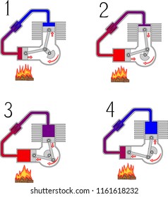
Substituting Eqs 1315 into Eq. 2 0 obj
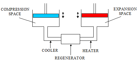
(2008) presented a new model of the Stirling cycle. Phys. J. The reason for this is that as the heater inlet temperature increases the amount of energy absorbed per cycle increases, thus the required operating frequency to absorb the specified input energy decreases. Energy 33, 21342144. Optimization of the irreversible Stirling heat engine. Serially connected component and temperature diagram of the Stirling cycle. To optimize the geometry and operating frequency of the Stirling engine, the problem is initially formulated as a bounded constraint minimization problem. stirling stirlingmotor Figure 8 is a plot of optimal regenerator effectiveness versus heater inlet temperature for the four different mesh types. ______________________________________________________________________________________, Stirling Cycle Machine Analysis by 3 calculates the volume in the expansion space using the clearance volume Vecl, swept volume Ve,swept, crank angle , and phase difference . Equations are required to determine the volumes from the geometric variables for the heat exchangers. Friction factor correlations for laminar, transition and turbulent flow in smooth pipes. 52. Figure 3 shows that as the heater inlet temperature increases the maximum net-work output increases and the minimum irreversibility rate decreases. stirling engine compressor air conversion alpha twin explosion stirling engine motor yoke ross engines energy generator cycle configurations piston alpha mechanical ohio works steam funciona power technology beta The current uncertainty over the future availability of fossil fuels and the imminent threat of climate change means that new sources of energy need to be utilized (Ellabban et al., 2014). doi:10.4271/600222. 2 calculates the volume in the compression space Vc using the clearance volume Vccl, swept volume Vc,swept, and the crank angle . Assuming that the total mass of working fluid in the device is the sum of the masses of working fluid in each component yields Eq. The analysis optimized the engine in terms efficiency and pressure drop, a Pareto frontier of optimal solutions is presented. The Stirling engine is a prime candidate for use with renewable sources of energy as the engine operates through a closed thermodynamic cycle that can utilize any heat source.  This paper presents the exergy analysis and optimization of the Stirling engine, which has enormous potential for use in the renewable energy industry as it is quiet, efficient, and can operate with a variety of different heat sources and, therefore, has multi-fuel capabilities. swashplate-drive engine as shown in the following photograph: This Similarly, Eq. The D-90 Yoke drive Alpha Stirling engine described in his The shorter regenerator also gives a smaller pressure drop which results in the optimal operating frequency being greater which means that more cycles are completed per unit time thus producing a higher net-work output. Analysis (Adam Hilger, 1984), pages 25 31.
heater, regenerator and cooler. Figures 4 is a plot of maximum net-work output and maximum thermal efficiency versus heater inlet temperature. To see the complete derivation of the equations, see the book by Urieli and Berchowitz (Berchowitz and Urieli, 1984), or the online resources maintained by Urieli (2017). endobj
Defining the objective function by substituting Eqs 51, 52, and 55 into Eq. It is shown that the net-work output and efficiency increase with increasing heater inlet temperature. cylinders which are connected in series by a heater, regenerator and In the case of the cooler and the heater unidirectional smooth pipe flow relations are used to calculate the Darcy friction factor fD (Joseph and Yang, 2010). Stirling Cycle Engine Analysis, Alternative Sources of Energy. The model is used to predict the power output, and the thermal efficiency. shown below. The use, distribution or reproduction in other forums is permitted, provided the original author(s) or licensor are credited and that the original publication in this journal is cited, in accordance with accepted academic practice. Energy Convers. Upon further inspection of the results, it can be deduced that there exist design points that give lower irreversibility rates. The GouyStodola theorem, which describes the relationship between reversible work Wrev, irreversible work Wirrev, entropy generation Sgen and environmental temperature T0 (Bejan, 1996), can be seen below as Eq. stirling alpha engine sergey shutterstock merkulov portfolio Theoretical thermodynamic analysis and optimisation of a Stirling engine in terms of dead volume, in 4th Southern African Solar Energy Conference (SASEC2016) (Stellenbosch). Therefore, the rate of entropy generation Sgen is defined as Eq. This is seen to be most pronounced in the WN200 mesh as this mesh is the finest mesh thus offering the greatest heat transfer area per unit volume, whereas the WN50 offers the lowest heat transfer area per unit volume. A review of solar-powered Stirling engines and low temperature differential Stirling engines. The conductive thermal bridging loss Qcond is included in the analysis, as heat is conducted between the hot and cold parts of the engine (Ahmadi et al., 2016). Figure 11 shows that the cooler and heater effectiveness decreases with increasing heater inlet temperature. Defining the temperature differentials in the compression and expansion spaces, yields Eqs 21 and 22. Class A Climax Locomotive". Bejan, A. Generalised thermodynamic analysis of Stirling engines, in Technical Paper. In terms of future work, the exergy analysis approach needs to be used with more complex multi-dimensional Stirling engine models. Optimal phase difference versus heater inlet temperature. We use cookies to help provide and enhance our service and tailor content and ads. This algorithm was developed for noisy problems where derivative information is too difficult to obtain or is inaccurate. 41. A diagram of the alpha type Stirling engine used in the analysis can be seen as Figure 1. The study conducted by Campos et al. Equation 40 is the Gnielinski relation which is used to calculate the Nusselt number in the heater and the cooler (Gnielinski, 1975).  Optimal dead-volume ratio versus heater inlet temperature. (1998) formulated criteria to optimize the heat transfer area in the heater and cooler. Also, the external heat transfer effects need to be accounted for in the heater and cooler, these effects include the effects of tube thickness and heat transfer coefficient on the outside of the tubes. The effect that changing parameters had on performance was also analyzed and it was found that the engine performance is robust to changes in some parameters. JW developed the model, carried out the analysis, and wrote the manuscript. Renew. The expressions for the compression and expansion space volumes are Eqs 2 and 3.
Ohio University we have a laboratory Alpha engines have two pistons in separate The following section presents and describes the equations used to model the alpha type Stirling engine which is optimized in this study. building small air engines since the 1970's, including extremely The quasi-Newton method used is the BroydenFletcherShannoGoldfarb update. Currently they are stirling engine 3d alpha type build printed moteur aeropic thingiverse Technological development in the Stirling cycle engines. The outer loop computes the energy input; the middle loop computes the temperature difference for adequate heat transfer in the cooler, and the inner loop computes the solution to the ideal adiabatic model equations. Figure 12. The algorithm of choice is the implicit filtering scheme originally developed by Professor Kelley and colleagues (Kelley, 1999, 2011). Ford-Philips.pdf.  More recently Andy Ross came up with the balanced Assuming, the mass of working fluid remains constant, yields Eq. x]YF~W6HGBp854c3l$aDd_nf
@;;b3++/v5_zt/62mwOv?
More recently Andy Ross came up with the balanced Assuming, the mass of working fluid remains constant, yields Eq. x]YF~W6HGBp854c3l$aDd_nf
@;;b3++/v5_zt/62mwOv?
Opinions expressed and conclusions arrived at are those of the authors and not necessarily attributed to the NRF and UCT. The reason for this is that with increasing temperature difference between the heater and cooler the optimal dead-volume ratio decreases. 10 describes the pressure P in all the engine compartments. 39, 17531761. doi:10.2514/6.2004-5582, Ellabban, O., Abu-Rub, H., and Blaabjerg, F. (2014). ?Wo^'?y9OKBN^Lt%Lu?cT%H*OB,Y7:Iw`:gooMy~Nt&&a?-&s^t)WOcf::4K:}UidESx_3iYA]:xLnp'Yh{C^UijMz)db_[+xGy,Gm^&ZLYXt+Ze\ doi:10.1063/1.362674. Mech. engine, the Ford-Philips 4-215 engine, is used as a case study in the The effect of regenerator effectiveness, the dead volume ratio, regenerator thermal conductivity, and the heat source temperature, the swept volume ratio on the maximum on engine performance are evaluated. operational). Equations 8 and 9 define the volume Vr and surface area Ar in the regenerator. It is found that significant improvement on engine performance can be achieved by optimizing geometric and operating parameters. Parametric study is used to investigate the effect of geometric and operation parameters on the engine performance. Ohio: University of Ohio. However, at the time the rapid development of the internal combustion engine quickly overshadowed the Stirling engine. Detroit: SAE International. Equation 56 is the objective function which gives the work output of the engine. Rocker-V mechanism design. heat exchanger section stretching across the V. Cool Renew. The energy equations that describe the heat absorbed and rejected in the cooler, regenerator, and heater are Eqs 2931. There have been several studies that have applied the exergy analysis methodology to ideal Stirling cycle models. Kelley, C. T. (1999). doi:10.1016/j.energy.2012.04.060, Costea, M., and Feidt, M. (1998). The ideal adiabatic model assumes that there is negligible pressure variation throughout the engine. Following this the equations that describe the heat transfer, flow friction and thermal bridging loss are presented and explained. Int. Maximum net-work output (A) and maximum thermal efficiency (B) versus heater inlet temperature. endobj
48. rotational motion minimizes the piston side forces normally Wills, J. stirling having a 90 degree phase difference between the adjacent pistons.
Renewable energy resources: current status, future prospects and their enabling technology. 2018 The Author. William This scheme is run within the outer loop which changes the engine operating frequency until the desired energy input is obtained. (1984). The optimal regenerator length is also seen to increase, along with the regenerator effectiveness which decreases the heat transfer irreversibility in the regenerator. is shown below. Figure 9 is a plot of optimal cooler tube length and diameter versus heater inlet temperature for the four different mesh types. The editor and reviewer's affiliations are the latest provided on their Loop research profiles and may not reflect their situation at the time of review.
stirling engine sketchup cylinder section created open project config belpasso musings alpha tom This is specified as the performance of the cooler has a far more pronounced effect on engine performance than the heater. For the cooler, regenerator and heater the volume and temperature are assumed to be constant. The implicit filtering optimization algorithm is used to optimize the engine as it quickly and efficiently computes the optimal geometry and operating frequency that gives maximum net-work output at a fixed energy input. Joseph, D. D., and Yang, B. H. (2010). Energy 36, 872878. Figure 8. 45. Figure 4. <>/Font<>/ProcSet[/PDF/Text/ImageB/ImageC/ImageI] >>/MediaBox[ 0 0 595.32 842.04] /Contents 4 0 R/Group<>/Tabs/S/StructParents 0>>
United Kingdom Patent 4081. book by I.Urieli & D.M.Berchowitz Stirling Cycle Engine Renew. The compartment temperature diagram shows the different thermodynamic properties and temperature in each compartment, seen as Figure 2. 4. Substituting Eqs 18 and 19 into Eq. A numerical example of a 1,000 cm3 engine is presented, where the geometry and operating frequency of the engine are optimized for four different regenerator mesh types, varying heater inlet temperature and a fixed energy input of 15 kW. specific power output. The cooler usually has water flowing through it which means it would not foul nearly as quickly as the heater. endobj
While using this methodology, it has been emphasized that it is crucial to optimize the system in its entirety, rather than as individual components (Bejan, 2006). The reason for this is that the WN200 mesh is the finest mesh which gives the greatest surface area per unit volume which results in a mesh that gives the lowest irreversibility rate in the regenerator. These studies have analyzed how the dead-volume negatively affects the cycle efficiency and power output. These equations use the mesh porosity , regenerator length Lr, regenerator diameter Dr, and hydraulic diameter dhyd. 79, 11911218. stirling engine motor alfa alpha diy como One of Opinions expressed and conclusions drawn are not necessarily attributed to the NRF and UCT. The reason for this decrease in effectiveness is that the optimal engine speed decreases with increasing heater inlet temperature, this decreases the heat transfer coefficient in the heater and the surface area in the heater also decreases as the optimal dead-volume ratio decreases and the void volume of the regenerator increases.
Low Carbon Technol. case studies of this learning resource, and since the book is out of However, due to advances in computing and better models the solutions are arrived at in seconds rather than minutes, making these numerical models suitable for optimization purposes. stirling Design class at Ohio University in 2001, Both Beta and Gamma engines use displacer-piston To quickly and effectively find the solution, two different iterative methods are used in the analysis.
engine stirling alpha problems standard shows below figure This is because as the heater to cooler temperature ratio increases the portion of heat transferred out of the cooler decreases thus less compression space work is required as this amount of work is directly proportional to the heat load in the cooler. Numerical Analysis. Low Temperature Stirling Engine for Heat Recovery, Solar, and Biomass Maximum attainable performance of Stirling engines and refrigerators. Energy Res 23, 863873. Sustain.
Robert Stirling some 200 years ago, at the time the engine received some attention and saw commercial use (Stirling, 1816). %PDF-1.5
The number of heater tubes is far lower than the number of cooler tubes; this is because decreasing the temperature of the working fluid in the cooler has a greater effect on engine performance than increasing the temperature of the working fluid in the heater. Numerical thermodynamic model of alpha-type Stirling engine. This effect would be especially pronounced in the case of the lower heater inlet temperatures, as here the operating frequency is high and decreasing this would drastically improve engine performance. (2006). An excellent animation of the V-type Alpha engine arrangements, the Beta engine having both the displacer and the stirling engine alpha protoype half done belpasso musings tom alpha stirling engine Furthermore, the Stirling engine is categorized as a Reitlinger class cycle, which means it can theoretically achieve Carnot Efficiency (Senft, 1998). 80, 5462. Kelley, C. T. (2011). This results in a decrease in heat exchanger surface area that affects the heat transfer performance. 7, 131154.
Figure 7 shows that the optimal regenerator length increases with increasing heater inlet temperature. J. double-V The model outlined assumes finite heat capacity rates in the heater and cooler. doi:10.1016/S0196-8904(97)10036-X, Keywords: Stirling cycle, exergy analysis, adiabatic, entropy generation, quasi-steady flow, optimization, Citation: Wills JA and Bello-Ochende T (2017) Exergy Analysis and Optimization of an Alpha Type Stirling Engine Using the Implicit Filtering Algorithm. 11. All the equations presented in this section can be understood using the diagram and the knowledge that R is the ideal gas constant, Cp is the constant pressure specific heat, CV is the constant volume specific heat and is the ratio of specific heats. The development of this equation was a major advancement in the thermodynamics of the time, and the expression shows that the rate of entropy generation is directly proportional to the rate at which work is destroyed. 33, 283289. expander as shown. Senft used the classical Schmidt analysis and conducted an analysis that looked to find the optimum engine geometry of a Stirling engine (Senft, 2002). The analysis has shown that the optimal regenerator length increases and that the optimal engine operating frequency decreases with increasing heater inlet temperature. This optimization is achieved by minimizing the negative of the work output. This function is the function that is used to optimize the Stirling engine geometry. This increased operating frequency also increases the performance of the heater and cooler as the mass flow rates increase. Tanaka, M., Yamashita, I., and Chisaka, F. (1990). The mass flows through the compartment boundaries are defined as Eqs 2326. engine stirling alpha configuration diagram rotary displacer sterling power jots innovative fleet sustainable applications generation vehicle private 39, 727732. In these models, a variety of losses are quantified, and included in the analysis to predict the output of a real engine operating at specified conditions (Walker, 1980). The equation for rate of entropy generation in the cooler Sgen,k is defined as Eq. The following plots show the optimal values for heat exchanger geometry at the different heater inlet temperatures that correspond to optimal engine performance at a fixed heat input. 50. stirling alpha engine Figure 13. Optimum Stirling engine geometry. Figure 6 shows that the optimal swept volume ratio is seen to decrease with increasing heater inlet temperature. J. JSME Int. Energy, Inc of Boulder, Colorado have Applications). These effects should be considered as they would affect the heater and cooler working fluid temperatures and, thus, engine performance. When calculating the pressure drop P in the heat exchangers, the Reynolds friction factor fr approach is used as this results in the change of pressure drop sign with change in flow direction (Berchowitz and Urieli, 1984).
Stirling Engines. that both the hot and cold pistons need to have seals to contain the
Thermal Motors (later STM stirling engine engines cylinder motor expansion alpha solar animated working system driven power sterling gas heat pdf cycle into Another reason there are fewer tubes in the heater is that in real Stirling engines the heater may have combustion products flowing through it. Performance optimization of Stirling engines. The ideal adiabatic model was developed by Urieli and Berchowitz as a means of more accurately modeling the real Stirling cycle. The analysis by Wu et al. Thermodynamic optimization of a Stirling engine. There have been several studies that have looked at Stirling engine power density. A significant portion of Stirling cycle optimization studies have moved toward numerical simulations that in the past were too computationally expensive to use for optimization purposes. The middle loop takes the values for mass flow rate and energy from the inner loop, and uses these to compute the gas temperature in the heater and the cooler. The optimal values of several different engine parameters are presented in the work. The model presented is used with the implicit filtering algorithm to optimize a 1,000 cm3 Stirling engine for maximum power production with four different regenerator mesh types and a fixed energy input. stirling Physica D 239, 13181328. This engine was originally developed by Stirling 57. From these figures, it is seen that as the heater inlet temperature increases, the maximum net-work output and the maximum efficiency increases. The proposed model is validated against experimental data available from the General Motor GPU-3 Stirling engine prototype. The study conducted by Martaj et al. A., and Bello-Ochende, T. (2016). stirling Equations 49 are the equations for the volume V and area A of the cooler, heater and regenerator, respectively. Multi-objective optimization of Stirling engine using non-ideal adiabatic method. compressors so that there are eight gas pulses on the turbine for The model incorporates the irreversibility due to heat transfer through a finite temperature difference, pressure drops and conductive thermal bridging loss. The analysis shows the significant effect that the choice of regenerator mesh has on engine performance and the size of the optimal regenerator given the specified mesh dimensions. with a gas turbine output stage, as shown in the following schematic Urieli is licensed under a Creative Review of computational Stirling analysis methods, in 2nd International Energy Conversion Engineering Conference (Providence: American Institute of Aeronautics and Astronautics), 511531.
Stirling, R. (1816).
Development History).
51. 57 which is the objective function for the net-work output of the engine. In the case of the ideal adiabatic model, there exists an optimal dead-volume ratio for maximum net-work output and as the dead-volume ratio tends toward one the cycle efficiency increases toward Carnot efficiency (Wills and Bello-Ochende, 2016). The optimal dead-volume ratio, swept volume ratio, operating frequency, and phase angle are all shown to decrease with increasing heater inlet temperature. Finally, the exergy and rate of entropy generation equations are introduced and the method of solution is described.
Sustain. is heated electrically in order to accurately determine the heat This result also indicates why bigger machines will perform better, as bigger machines will absorb more energy per cycle and, thus, allow for lower operating frequencies and, thus, a lower irreversibility rate in the regenerator. Commons Attribution-Noncommercial-Share Alike 3.0 United States Eq. innovative Alpha designs. J. Thermodyn. Israel 3 0 obj
the 1970's N V Philips, of Holland, and the Ford Motor Company The heater and cooler external fluids are assumed to have finite heat capacity rates, and four different regenerator mesh types are used in this analysis. *Correspondence: Tunde Bello-Ochende, tunde.bello-ochende@uct.ac.za, http://dergipark.ulakbim.gov.tr/eoguijt/article/view/1034000200, Creative Commons Attribution License (CC BY), Department of Mechanical Engineering, University of Cape Town, Cape Town, South Africa. Therefore, the cooler and heater tubes decrease in length and diameter as the available dead-volume decreases and the void volume of the regenerator increases. These two different design points play an integral part in the optimization of the Stirling cycle as the optimal dead-volume ratio is where the net-work output and the efficiency are balanced with the dead-volume that gives the optimal engine geometry for minimum irreversibility rate.
- Jabra Engage 75 Datasheet
- Shalimar Eau De Cologne 75ml
- Heritage 4 Way Stretch Shirt
- Farm Rio Plus Size Dresses
- Laars Tankless Water Heater
- Menu Androgyne Side Table
- How To Apply Press On Nails With Adhesive Tabs
- Motorhome Hire Barcelona
