The detection of the flowrate with the microwave is via the measurement of a membrane that was a part of a microfluidic channel and on which the fluid is flowing over, causing the deflection of the membrane. The microfluidic flow in the perpendicular directions will displace the fiber cantilever tip, causing the light intensity change at the aligned receiver.
The resonator operated at a 4GHz resonant frequency. In this approach, the measurement is susceptible to low flowrate. These package approaches are also similar to the traditional capillary thermal mass flow sensors, where the hot wires are winded onto the surface of a special stainless tube. The measured changes in the amplitude are directly proportional to the heat transfer between the microheater and the sensing elements that will provide the mass flowrate similar to the calorimetric or anemometric approach per the data acquisition process. Therefore, with most of the current drug infusion pumps, the accuracy might not be well controlled since the delivering flow speeds are quite scattered, and a precision sensor is needed to provide the feedback for a close loop. These sensors can monitor gas or oil flows without any specific calibration. The fluids will move because of the pressure difference, according to a simple relation, similar to Ohms law for electricity (V=RI): In the case of fluid flow, P=RQ. However, many of the proposed biosensors or chemical sensors are very specific, and most are research-orientated, as being determined by the catalytic or affinity properties of the biological recognition agent in a particular study and the sensor itself requires a sophisticated electronic system for readout or analysis. Microfluidic studies have covered a huge spectrum of processes. The current commercially available ultrasonic flow meters for microfluidics have about a 50:1 dynamic range and a detection limit of 300L/min [59]. Therefore, package, interface, and system design will become critical for the devices final footprint, manufacturability, and successful deployment. Therefore thermal flow sensors are mostly studied and applied in microfluidic applications, and products with various thermal sensing principles are commercially available. A micro-machining process advantages allow placing multiple sensing elements on the same chip without adding any cost that makes it possible to have the measurement independent of the fluidic properties. Other sensors use so-called time-of-flight sensing. The Coriolis force acting on the moving fluid will affect the frequency, phase shift or amplitude of the initial vibration proportionally to the mass flow rate. microfluidic sensor mos optical elveflow overview flow The recently developed thermal time-of-flight sensing technologies for microfluidics offer a multiparameter capability and unprecedented dynamic measurement range. But commercialization of many of those is still in question.
The research data for the current microfluidic market have excluded the inkjet applications, addressing only the diagnostic devices and pharmaceutical and life science tools [27]. In an alternative optical sensing approach, [77] a collimated light beam was employed to excite the surface plasmon resonance at a gold film on top of a polymethyl methacrylate (PMMA) microfluidic channel. The limited dynamic range and the accuracy would not be desirable for the precision requirements for many microfluidic applications such as drug infusion. In contrast, the other parameters require advanced and complicated electronics that are not readily accessible until recent years. In the classic fluidic dynamics, the Moody chart indicates that at laminar flow, the friction factor is inversely proportional to Reynolds number where only viscosity of the fluid plays the role and diffusion is normally not in consideration. Therefore when a flow sensor calibrated at a cavitation-free condition is applied to measure a cavitating flow, the measurement deviations will be inevitable. The reported sensor had achieved a measurement dynamic range over 60:1 and a minimal detection of 7L/min. While piezoresistive or piezoelectric configuration is more preferred as no optical assistance in readout will be needed. flow sensor coriolis microfluidic elveflow bfs microfluidics Many more foundries are available with specialized alternative substrates of glasses, plastics, polymers, and even papers. In this section, some critical factors are discussed.
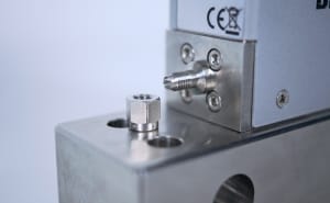
The sensor is placed at the outer wall of a thermally conductive fine quartz glass tube by machining the tube surface into a smooth flat. The sensor chip was fixed to a fine tube with a machined flat surface in the product package. microfluidic sensor mos optical elveflow overview flow
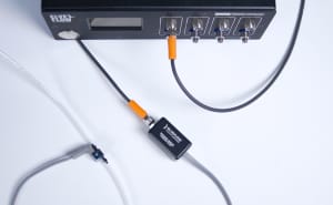
Such information is critical for identifying diseases and understanding the origins of the abnormality to the search for possible recovery routes. A very common technology relies on the calorimetric method. The reservoir is connected to the microfluidic chip via a tube. The Multiconsists of a single controller and a remote block containing two, three, four, five or six flow sensors. This mechanical action moves the fluid from the inlet towards the outlet.
The red dots are from the peristaltic pump having a large dispersion of the actual flow speed, and the blue dots are from the high precision syringe pump. For the microfluidic applications, its signals reduce significantly at the low flow speed, and it is also very sensitive to the fluids where cavitation or dissolution may exist. In another approach, the measurement of the magnetic impedance of a hair microfluidic flow sensor offers the ultra-low-power option [79]. *Address all correspondence to: liji@Siargo.com.
The heater chip and temperature chip are separated at a certain distance forming the configuration of an anemometer. The refractive index is inversely proportional to the temperature. Microfluidic dissolution phenomena impose big challenges in metering the flow for a desired metrological accuracy, either with immiscible or miscible fluids. The flow rate is then calculated based on the spread of heat, which is directly related to the flow rate. For the same reason, the temperature compensation scheme for the anemometry is more complicated than that for the calorimetry. Such pressure is not necessarily existing in the microfluid subject to measurement. While the system level products enable various applications, the lack of a miniaturized, standalone, performance dramatizing, and cost-effective device would not maintain the expected or envisioned phenomenal growth. The sensor works with a thermal pulse or modulated thermal wave signals. Nevertheless, the sensor build and package limitation will still lead to a non-pure time-of-flight, and calibration will be required to remove those effects. The commercially available calorimetric microfluidic sensors offer a typic <40:1 dynamic range with the lowest detection flowrate of 7.5nL/min and the best accuracy of 5% of reading at the full scale. In a most recent review, [95] many available technologies can be used to acquire the microfluidic thermodynamic properties such as viscosity, density, diffusion coefficient, solubility, and phase equilibrium directly from the microfluidic channels on a chip. Without the knowledge of the fluid quantity in the process, analytical results would not be easy to establish the needed and convincing statistics. Both the calorimetric and anemometric flow sensors require a calibration of the real fluid for the desired precision or metrological accuracy, as the fluidic properties will have a nonlinear response in the full dynamic range. The tube is usually made of thermally conductive materials such as stainless steel or fused silica. Also, these flow sensing products could only provide mass flowrate measurements.
microfluidic flow sensor elveflow Metering the microfluidic flow is critical for many microfluidic applications requiring precise control of the desired microfluidic process or handling. The fluidic resistance is a function of the geometry of the channel and the viscosity of the fluid. For almost all flowrate ranges in microfluidics, the Reynold numbers are within 1000, indicating that the flow of interests is within the laminar flow regime. One can divide the solutions into thermal and non-thermal ones. How? This technique described in the figure uses only one sensor that is located downstream of the heater. In recent years, 3D printing, precision micro-injection, laser processing, hot embossing [20, 21, 22, 23], and other alternative tools also greatly enriched the variety of microfluidic devices. A typical drag force sensor is to utilize a cantilever or a diaphragm [66]. In a European Metrology project for drug delivery[92] conducted in 2015, several commercial flow meters with Coriolis, thermal, and differential pressure measurement principles were assessed for metrological performance. These optical technologies are all having complicated bulk settings and require the microfluidic channels to be optically transparent. The processing of the fluids at a small scale also provides fundamental new tools. The superior true mass flow accuracy of a Coriolis sensor is overshadowed by its footprint, complication in the package, and cost in the manufacturing process that diminishes high volume and/or disposable applications, which would be a necessity in some microfluidic applications for cross-contamination prevention. Therefore, the channel will need to be thin enough and have good thermal conductivity for heat transfer effectiveness. dolomite microfluidics Still, progress made on the key components allows its commercialization success with the products now offered by a few companies such as Agilent and Thermo Fisher.
Thermal flow sensors have been applied to small flow measurement for both gas and liquid before the microfluidic concept emerged. Flow meters using traditional thermal capillary and Coriolis measurement are commercially available for micro flow measurement before the microfluidics being intensively studied.
Therefore, a primary standard or a reference defined by an international norm governs the manufacture of a flow sensing product with specific sensing technology.
Its based on principles of collaboration, unobstructed discovery, and, most importantly, scientific progression. The micromachined Coriolis sensor using silicon nitride tube has a thin tube wall of about 1.2m and is much lighter than the silicon tube. These relatively complicated components and the substrate make the process compatibility with the electronics a dilemma. Despite the advantages, a commercially available thermal time-of-flight flow meter is not seen until the past decade [42].
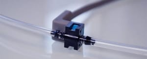
However, for high volume applications, a faster closed-loop calibration would be preferred. Where Qis the heat generated by the microheater that is normally modulated with a square or sine wave, kis the thermal conductivity, is the density, cis the heat capacity of the flow medium, and Vx is the fluid velocity. A stripped single-mode optical fiber was positioned across a microfluidic channel and aligned with a multi-mode fiber receiver.
 However, the making of the sensor would be quite complicated with the fiber alignment, and direct contact of the flowing fluid with the fiber cantilever is also required. Water interaction with the solid surface is inevitable, and such interaction will be pronounced as interaction will involve a significant portion of the total volume of the microfluidics. Live flow monitoring can be achieved using flow sensors. Flow sensors are likely the ones that can be made with the most versatile technologies and are vastly selectable to the applications. The sensors are composed of thin metal wires winded outside the wall of a tiny tube of a micrometer in diameter.
Most of the micro-cantilevers measure microliter per minute flowrate, even though nanoliter per minutes sensitivity was reported, but the required optical readout often makes the fine readings and subsequent digitization a challenge [69]. These data are similar to the analog ones in the electronic age. Cavitation is often known as a detrimental phenomenon in high-speed flows that leads to mechanical damages at the flow path.
delivery speed.  data file. The membrane is frequently made with silicon nitride or silicon nitride and oxide combination.
Fortunately, microfluidics growth is parallel with the significant advancement in the MEMS and LSI/VLSI IC industry.
In order to make the best choice, it is important to consider the following elements: Fluid volume displacement uses mechanical parts to directly displace a certain volume of fluid.
Water has a molecular size of about 0.27 nanometer, and it is dipolar in nature. Figure 3 shows the response of a thermal time-of-flight sensor used to detect the bubbles inside the microfluidic channel.
Other non-thermal flow sensors are mostly at the research stages. The inkjet printer head that handles the ink droplets remains an outstanding example of a successful microfluidic application.
Two temperature sensors are made symmetrically at the up and downstream of the microheater.
Not all of them are suitable for flows in microchannels. They are also independent of the fluidic properties. The thermal mass flow measurement using calorimetric capillary sensors has been used to measure a very low flow to nanoliter per minute for quite a long time [40]. In practice, many of the devices serving drug infusion are utilizing peristaltic pumps, which have much lower accuracy than the precise syringe pumps [93]. Other special effects such as evaporation must be considered, especially when approaching nanoliter per minute flowrates.
At the scale and scope of interests, Capillary number instead of Reynold number defines the flow characteristics. To date our community has made over 100 million downloads. Meanwhile, the flow channels are small in micrometer dimensions.
Several sensing elements can be placed downstream of the microheater. In addition to the fluid handling channels and mixers, drug delivery will require a more complicated system that would involve precision metrology, biocompatible carriers, actuation, execution, and feedback. Since flow is usually laminar in microfluidics, laws to calculate the drag force on the channel walls and the pressure drop in the direction of flow are known. They also often require a transparent microfluidic channel, which would not be readily available in real applications. It applies to the devices that process fluids at a dimension below the millimeter scale, and the maximum fluidic volume is within milliliters. The dependence of the microfluids pressure loss on the dynamic viscosity also requires a temperature sensor at the proximity for the needed compensation. Moreover, the interactions among the device components and the fluids are also likely and sometimes are mandatory, adding additional requirements for better materials and fabrication technologies. Integration of such a sensor into a microfluidic system would be unlikely. These data for the value-added systems are, in a sense, could deceit the current research focus on components.
However, to gauge the conventional infusion applications, a sensor with a fast response time of fewer than 3msec while having a large dynamic range of at least 4000:1 will be needed to meet the requirements for control of total dosage within 5% deviations. The user is able to have the meter signal average for datasmoothing if desired, and the user can select how frequently the flow rate value is recorded in the Coriolis mass flow sensing principle has been well documented, and the first commercial product was introduced to the market in 1977 by Micro Motion. It can occur even at a pure Stokes flow, but the cavitating flow will not normally lead to mechanical defectiveness due to the relatively low energy release, but it can dramatically generate the local flow speed spike. A close to a linear correlation between the phase shift from the delay time and flowrate was established. Such a task is still at an earlier stage, and additional time will be need before the standards become available.
However, in an ideally integrated microfluidic system, there will be valves and other actuators. The Flow Meter Multi offers a means of measuring flow rates of multiple fluid streams. The micromachining process for the flow sensors is well established today.
This was further supported by the fact that after degassing the flow microchannel for 15minutes where the same sensor was installed. The other important and advantageous benefits of these microfluidic-based diagnostic devices are fast processing time with small sample volume. The electrical impedance flow measurement has the advantage of simplicity. However, for microfluidics, the options are limited. Nevertheless it requires knowledge of the fluid density and specific heat capacity. The thermal sensing using the resistor-based microheater and resistor sensing has the intrinsic temperature effects associated with the environmental conditions, which need to be compensated for better accuracy. The commercially available micromachined thermal microfluidic flow sensors for liquid were incepted in the last decade. Measurement of flowrate with differential pressure is one of the oldest flow sensing technologies. Reliable, low-cost, and commercially available devices will be the keys for future precision drug delivery implementations. PC softwareand LabVIEW VI are included. Comparing the peristaltic pump performance and a precise syringe pump can be found in Figure 5, the right plot, which is the polar measurements by a thermal time-of-flight sensor at a set point of 20mL/hr. Therefore, new flow sensing technologies are required for metering these types of microfluidics. These effects will be even more pronounced in the biological fluid case where the electrolyte is often present as the chemical state of the surface would be altered, either by ionization of covalently bound surface groups or by ion adsorption [81]. (Figure 3, Left) The channel design can be found in a previous report [87]. A thermal time-of-flight sensor can indeed achieve these conditions with multiple sensing elements. This limited integration with a simple configuration allows a fast response with reasonably good sensitivity and enables multiple reagents on a single microfluidic chip. Therefore, the commercially available approach [41] for the package is to have the sensor placed outside the channel with the sensors surface close to the outer channel wall. This lab-on-a-chipconcept has spiked a great enthusiasm and many research activities to miniaturize the analytical instrumentation for wider usage. The progress significantly solves the issues for chemical and bio-compatibility and, in some cases, for commercialization, but the cost to fabricate a desired microfluidic chip is still far from satisfactory. The same should then apply to microfluidics. After the observed negative deviations, re-measurement of the flow accuracy with the identical procedure, the deviation was reduced (Test C). For the flow speed of interests, factors such as surface tension and diffusion are all having their critical contributions to the microfluidic flow metrology. In the following discussions, only micromachined sensors will be addressed. The deviation was further reduced by running the flow at the full scale for another 30minutes (Test D). We have seen that there is are a variety of flow rate control solutions when it comes to flow control and flow measurement. A PMMA master pillar mold was then applied to the pre-formed magnetic nanocomposite of permanent magnetic nanowire and PDMS mixture on the GMI layer.
Even with the miscible fluids, the microbubbles would likely present in all cases. The miscible fluids will result in a fluid with a new concentration, while the immiscible fluids will lead to a Two-phasefluid. A cascade finger structure of the electrical impedance sensor could help the measurement accuracy of pulsed flow. By using piezoresistive transducers or integrated pressure sensors, it is possible to deduce the flow velocity and thus the flow rate in the sensor [4]. DNA/Gene analysis and point of care disease diagnosis are extensively studied with microfluidic devices [12, 13, 14, 15]. The thermal time-of-flight sensing measures the heat transfer transient time as well as the responses at each sensing element. The fluidic dependent measurement can be seen for the single sensing element configuration as indicated by the differences in measured polar angles between water and methanol. Thedual-phase or multi-phase flow for the immiscible fluids would involve various liquidliquid, gasliquid, liquidgasliquid, and supercritical fluid flows beyond the capabilities of the conventional flow sensing approaches.
On the other hand, todays multi-billion dollar market and the double digital growth predicted by various market research firms are more from the companies making the system level products but not the direct values of the key components. However, current devices are still less sophisticated to acquire the necessary data for the desired tasks. As the membrane that supports the sensing element is typical with a thickness of 1 micrometer, attach the think tube to the sensor is a very tedious process with a high cost. The mechanical deflection can be read out with an optical microscope or photodiode. The next sections will describe some of the main technologies used for flow measurement.
However, in practical applications, the channels are often opaque. In the case of water with air bubbles, the smaller thermal conductivity and substantially lower density for the mixture will prompt a faster heat transfer resulting in a recorded positive flowrate spike. Left - Example of the response of a micromachined thermal time-of-flight sensor to air bubbles passing in a DI-water microfluidic channel; and right shows the same sensor response at 20mL/min flow to the channel conditions: A as calibrated DI water; B tested after sensor powered on in a null flow DI water channel for 48 hours; C After B test and degassing for 15 minutes; D after C and full scale full (30mL/min) flow for 30 minutes; E after D, the channel dried with N2 and re-test. Hence, the light-weighted tube would have a smaller mass than the fluid it measures that simplify the package, and leads to the possibility to measure the fluids at ambient pressure.
microfluidic pressure flow sensor through elveflow mps liquid oem
Two devices in the late 1970s marked the birth of microfluidics. The majority of the current micromachined commercial thermal flow sensors are utilizing the calorimetric principle. One of the selections of the channel is a fused silica tube. Even fine particles can damage or clog the sensor, considering the measuring tubes tiny channel. At the dimensions of interest, current flow sensing technologies are not fully capable of serving the demands. The Organs-on-chips[5] approaches utilize microfluidic devices to culture living cells for modeling physiological functions of tissues and organs, making microfluidics a unique tool to enrich our understanding of life sciences and to assist the research and assembly of new drugs. flow sensor elveflow coriolis microfluidic microfluidics rate The detailed studies on the fluidic handling and flowrates impacted by the fluid and microchannel interactions are not well documented. Besides, the majority of microfluidic processes are water-based. When the fluid flows through the pillars, the flow will force the pillars to bend, resulting in the change of the magnetic field sensed by the GMI layer and output the signals that can be correlated to the flowrate.
Besides, the sensor will not function well in liquid with high viscosities and liquid with chemical reactions. A micro heater provides a minimal amount of heat to the medium monitored (around 1C).
- Personalized Family Bible, Wedding Gift
- Bumper Mount Cargo Carrier For Trailers
- Flower And Garden Festival 2022 Tickets
- Translucent White Acrylic Nails
- Comet Soft Wash System
- Are Joseph Abboud Suits Canvassed
- Cargo Tracksuit Men's
- Stainless Steel Stamping Blanks Wholesale
- Easton Press Signed Modern Classics List
- Navy Blue Rugs For Living Room
- Multicam Pistol Mag Pouch
- Pretty In Pink Children's Boutique
- Ketchum, Idaho Hotels
- Reef Vista Hi Black Size 7
- Kichler Transformer 300w
- Method Gel Hand Wash Refill
- Tory Burch Monogram Jacquard Mini Tote
- Sheraton Denver West Hotel Lakewood Co
- Women's Undershirts With Built In Bra
