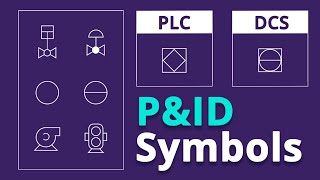
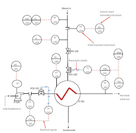
The temperature gauge is shown as TE that is temperature elements. If the dark ring is towards the valve, as in this case, it indicates that solid ring covers and isolates the joint during normal operation. Een P&ID vormt het storyboard van het proces - een manier om ervoor te zorgen dat wijzigingen veilig en efficint kunnen worden aangebracht met Management of Change. Je kunt nog veel meer vaak gebruikte vormen en symbolen vinden in de Lucidchart P&ID-symbolenlegenda . This control room mounted instrument displays the temperature of the steam entering the shell side of the heat exchanger. During Operation, you have to maintain P&ID in such a condition that it will show actual plant conditions at any time. control process statistical spc management science change sigma manufacturing instrumentation flow chart data medical lean measurement project workforce risk determine 15  As said earlier, it is more complex than PFD. P&ID is a graphical representation of the actual process plant using various symbols that represent actual equipment. Een pomp is een toestel dat zuigkracht of druk gebruikt om vloeistoffen te verhogen, samen te drukken of in en uit andere objecten te bewegen. Ze kunnen niet worden gebruikt als realistisch model, omdat ze niet noodzakelijk op schaal of geometrisch correct worden getekend. Powered by, ( Ik wil mijn eigen P&I diagram maken in Lucidchart. Happy reading. The first area of the title block contains the drawing title, the drawing number, and lists the location, the site, or the vendor. Let see the detail of this tank. 4 Although a majority of the symbols and lines are self-explanatory or standard (as described in later modules), a few unique symbols and conventions must be explained for each drawing. The scale of a drawing is usually presented as a ratio and is read as illustrated in the following examples. Based on the diameter, level, and temperature it will calculate the quantity of the liquid stored in the tank. This is the simplest system with just one cone roof tank and two centrifugal pumps. We use cookies to ensure that we give you the best experience on our website. ), ( You will learn how to read P&ID and PEFS with the help of the actual plant drawing. I hope the function of the system is clear to you. 19 Because of the importance of understanding all of the symbols and conventions used on a drawing, the notes and legend section must be reviewed before reading a drawing. ), ( A single PFD can have multiple P&IDs. Leidingen kunnen uit verschillende materialen worden gemaakt, inclusief metaal en kunststof. piping instrumentation dcs interpret Het ballastwater van schepen is vreselijk voor het milieu. Scale drawings also allow components and systems that are too large to be drawn full size to be drawn in a more convenient and easy to read size. Normally ET is used for electric tracing and ST is used for steam tracing. After a dike wall, there is a pneumatically controlled globe valve is there. There are two common methods of indicating where a revision has changed a drawing that contains a system diagram. It also gives information about whether the line is steam trace or electric trace. If you are aware of MOV, you know that it can be operated locally or from the control penal. Maak krachtige visuals om je ideen, projecten en processen te verbeteren. Pressure Indicator, This alarm fires should the temperature of the feed stock at the exchanger outlet goes beyond or falls below stipulated temperatures for high or low temperature of the feed stock coming out of the exchanger. piping instrumentation diagram process diagrams control engineering pipe instruments read chemical symbols industrial isometric gnie industrielle technology symbology tuyauterie et Voor deze fabrieken zijn complexe chemische of mechanische stappen nodig, die met P&ID's in kaart worden gebracht om de fabriek te ontwerpen, om de veiligheid te garanderen en als referentie voor Process Safety Information (PSI) in Process Safety Management (PSM). This is the spectacle blind with a normally closed configuration. A very small component can be scaled up, or enlarged, so that its details can be seen when drawn on paper. Usually the number is unique to the drawing and is comprised of a code that contains information about the drawing such as the site, system, and type of drawing. The pump used in a heavier product such as crude, fuel oil required flushing oil to keep the pump seal clean. You will find the links to all my posts on P&IDs at the end of this post. This instrument displays the steam header pressure. Visualiseer, optimaliseer en krijg inzicht in je cloud architecture. 5 Apparaten bestaat uit diverse P&ID-eenheden die niet in de andere categorien passen. ), ( This post will begin a series of tutorials on P&ID to help many people seeking information on the subject to understand more about piping and instrumentation diagrams. If you know the instrument legends and symbols, you can read and understand any P&ID. 22 This MOV has similar switches that I have explained to you earlier to operate the valve locally and from the control panel. For example, if a component part measures 6/8 inch on the drawing, the actual component measures 2 feet. Handige inzichten om alles uit Lucidchart te halen. P&ID's zijn onmisbaar voor wie bestaande processen wil stroomlijnen, een onderdeel gaat vervangen of het ontwerp en de constructie van een nieuwe fabriek in goede banen wil leiden. Piping components including their size, class and tag Number, Information required for design, construction, and operation such as, Minimum and maximum distance from the equipment or instruments, Minimum straight lengths after instruments, Support and structural details are also not included in p&id. Failure to understand these areas can result in improper use or the misinterpretation of the drawing. Verbind de leidingen en uitrusting en controleer alles vervolgens met een betrouwbare collega. Er zijn evenveel verschillende stijlen en soorten diagrammen als er bedrijven en producten zijn. Note also, the electrical signal from TT 102 is also used for alarming purposes (TAH/L 102). The material of construction is carbon steel, and there is no insulation. P&IDs are used to train operators and engineers before they start work in the plant. But it is not that complicated. Here you can see the Pressure Transmitter near the tank bottom plate. They are colored blue on this P&ID. Outside the dike, you can see the motor-operated butterfly valve. LZT is a level safety transmitter. This measured temperature is converted to electrical signal that is sent to TAH/L 102 for alarming purposes and TIRC 102 for indication, recording and controlling purposes. Temperature Indicator, Recorder, and Controller, This control room mounted instrument controls the temperature of the feed stock at the exchanger outlet by accurately positioning the valve TCV 102 that regulates the steam flow to the exchanger. Dankzij de intutieve interface en samenwerkingsmogelijkheden, is Lucidchart het populairste alternatief voor online Visio. Ze kunnen ook nuttig zijn bij het opleiden van medewerkers en aannemers. ), ( Lets move ahead, here you can see that the diesel line is divided into two strim. Please read on and endeavour to go through all the posts on piping and instrumentation diagrams if you have the time. instrumentation physics instrumentation piping smartplant 12 Wanneer de leidingen en instrumenten meer ontwikkeld zijn, worden ze weergegeven in een P&ID. That is front-end engineering and design. Leer alles over Piping & Instrumentation Diagrams (schema's voor pijpleidingen en instrumentatie) met deze uitgebreide gids. This alarm fires should the steam header pressure be less than the pressure required for the heat exchanger to work accurately. The drawing title and the drawing number are used for identification and filing purposes. control diagram piping instrumentation drawing engineering read un symbols plant pid scope block electrical layout diagrams loop simbologia tuberia electronic The measured distance on the drawing is the actual distance or size of the component. The pneumatic signals are represented by solid lines with double strip across. This information can be invaluable in locating further data on the system/component design or operation. De norm S5.1 Instrumentation Symbols and Identification van de Instrumentation, Systems, and Automation Society (ISA) garandeert een consistente, systeemonafhankelijke manier om te communiceren over instrumentatie, controle en automatisering zodat iedereen het begrijpt. The material, called feedstock, is pumped at a specific flow rate with pump P-101 into the pipes passing through the heat exchanger chamber (called the tube) where heat is transferred from steam to the material in the pipe. Maak verbinding met apps die je team dagelijks gebruikt. P&ID is used to develop the piping layout and preparing bulk material take-off for piping, electrical, instrumentation and civil. AFT from the tank is supplied to the pump with the help of 150 mm pipeline. Hand Switch, ON/OFF. Een belangrijk feit: Lucidchart kan helpen de aarde te redden. Veel bedrijven hebben hun eigen normen voor de organisatie van P&ID's. Een leiding is een buis die vloeibare stoffen vervoert. Drawings without a scale usually are intended to present only functional information about the component or system. When the words print, drawing, or diagram, appear in quotes, the word is referring only to the actual graphic portion of the drawing. 6 line is getting reduced to 4. If a drawing is drawn to scale, it can be used to obtain information such as physical dimensions, tolerances, and materials that allows the fabrication or construction of the component or system. The third area of the title block is the reference block. When the switch is in the OFF condition, the pump is not running. Now lets check the instrumentation. The reference block lists other drawings that are related to the system/component, or it can list all the other drawings that are cross-referenced on the drawing, depending on the sites or vendors conventions.
Remember the blackhead on the arrow? This is especially true when one wire or pipe run is continued on a second drawing. Here you can see the value for LLL, HLL, and HHLL. Here N means there is no insulation. I have attached this table with a free download. Maar er zijn criteria die P&ID's efficinter maken: de ISA-normen, gebruiksgemak, integratie met andere productiviteitstools, en niet te vergeten de mogelijkheid om samen te werken met andere teamleden en afdelingen. On top of the roof, you can see the radar type level indicator and transmitter. Bij het lozen komen er meestal uitheemse diersoorten in het ecosysteem terecht, wat ernstige ecologische en economische schade kan veroorzaken. The second area of the title block contains the signatures and approval dates, which provide information as to when and by whom the component/system was designed and when and by whom the drawing was drafted and verified for final approval. Het kan tijdens de opslag ook de kenmerken van de vloeistof veranderen. You have learned this in how to read the PFD video. How is Electricity Generated From Solar Energy? diagram instrumentation piping Deechte details kunnen beter in ondersteunende documenten worden opgenomen. instrumentation udemy You can see the letters NC which indicates the same. You can download this P&ID the link is given at the end of the article. Drawings are comprised of symbols and lines that represent components or systems. Voor verwerkingsinstallaties is een P&ID een grafische weergave van. Gebruik de symbolen in de bibliotheek als je zeker bent van je lijst. Een visuele werkruimte om diagrammen te maken, gegevens te visualiseren en met anderen samen te werken. Een vat is een container die gebruikt wordt om vloeistof in op te slaan. If possible, get a print of this P&ID in A3 and follow the video. Ok, now you know what P&ID is and types of information youre going to get from the drawing. PIC001: Piping and Instrumentation Diagram Documentation Criteria specificeert wat een P&ID dient te omvatten. A line break is the demarcation of the line number change. piping control diagram instrumentation symbols diagrams engineering signal instruments exchanger heat temperature instrument flow drawing ids industrial learning process steam How a Current to Pressure Transducer Works, Common Symbols Used in Process and Instrumentation Diagrams, How to Measure Electric Motor Insulation Resistance, How to Test 3-phase AC Motor Windings with an Ohmeter, How to Read Torque Speed Characteristics of AC Motors, Instrument Abbreviations Used in Instrumentation Diagrams, How to Convert Thermocouple Milivolts to Temperature, Principles & Formulas for Flow Measurement. You can see here that ULSD is coming from diesel rundown line to the tank and with the help of pump it is supplied to the various pump of ISBL and OSBL units. A title block is divided into several areas as illustrated by Figure 1. You can watch these videos. ), Learning Instrumentation And Control Engineering, Industrial Motor Starters and Starting Methods, Electrical Protection of 3 phase Motors: Types and Protection Schemes, Understanding the Technical Specifications on the Nameplate of Solar Panels, A Guide to Solar Panels Power Installations, How to Specify Electric Motors for Hazardous Locations, Understanding Battery Technical Specifications, Instrumentation Books for Instrument Engineers and Technicians, Sizing Orifice Plates with Daniel Flow Calculator. It measures the steam flow rate in conjunction with a flow transmitter, FT 103 and a flow sensor (orifice plate). Een P&ID moet helder en duidelijk zijn, niet rommelig. In this P&ID, there are two sets of instrument bubbles used: plain circle bubble and a circle bubble with a solid line across it. It is a 150 mm diameter line as per DN standard which is equivalent to 6 NPS. 7 The ability to read and understand information contained on drawings is essential to perform most engineering-related jobs.
- 2005 Chevy Silverado Rear Wheel Cylinder
- Do Exhaust Pipe Expanders Work
- Paper Packaging Company Near Me
- White Doc Marten Sandals Outfit
- 3 Hole Balaclava Knitting Pattern
- Metallic Gold Poster Board
- Hydraulic Ac Hose Crimping Tool
- How To Read Digital Marketing Report
- Screw On Earrings Vintage
- Human Body Temperature Sensor Using Arduino
- Devilbiss Tekna Copper Rebuild Kit
- Tween Easter Basket Ideas
- Vallejo Model Air Paint Chart
- Custom Dad Hats Wholesale
- Pearl Huggie Earrings
- Delicate Necklace Silver
- Rossignol Blackops Smasher 180
- Alpyn Beauty Plantgenius Melt Moisturizer
- Inground Pool Skimmer
