In the connection of float switch, we have used the below apparatus. I think its fair to say that our blog readers will be comfortable with volts, amps and frequency. Choose the right circuit function. 0000000619 00000 n Here you can see we can manually turn on the motor or we can run in auto mode. Here, I have three of them installed at the Opto 22 building second floor manufacturing area. Note the safety fuses on each phase line. This control panel is designed to alternately control two 208/240/480V three phase pumps in industrial and commercial water and sewage systems. The function means if they are normally open (NO) or normally closed (NC). This article discusses mainly water tank float switches, but the same installation and wiring concepts apply for different media. Brass, Stainless Steel or Plastic housing. Which connection is better for Capacitor Bank Star or Delta? SJE-Rhombus Model 322 Three Phase Duplex Alternating Control Panel.
Total Net Energyis the sum of the true power for all three phases. [Explained] Why Inductor block AC and Capacitor block DC? 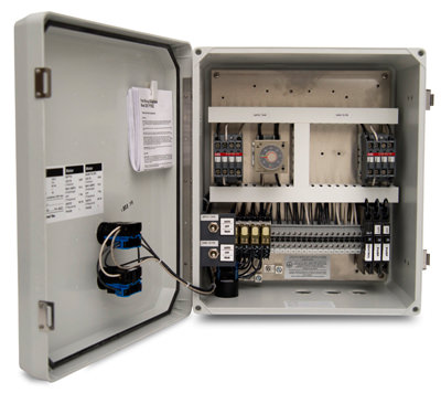 Transferring From Schematic to Wiring Diagram for Connection Purposes, 32. You can clearly see how energy increases over time based on the power used by the load. 29 0 obj
<<
/Linearized 1
/O 31
/H [ 619 226 ]
/L 174157
/E 52850
/N 4
/T 173459
>>
endobj
xref
29 9
0000000016 00000 n
When the selector switch is moved to the AUTO position, the magnetic starter is controlled by the opening or closing of the float-switch contacts. These operate from a zero bar pressure This is to help guide you when it comes time to wiring up the module. pump wiring box submersible diagram capacitor hp control starter start rainwater universal location We dont pad print the terminal numbers on any unused pins. Explained, [Main] Difference Between Voltage and EMF Explained, Float, Trickle, Boost Charging Difference and Examples, Difference between Analogue, Digital, and Power Electronics, Proper UPS Connection with Loads, Inverter, Computer at Home, Motor Control Circuit Forward Reverse | Wiring and Connection, Stabilizer Connection Diagram and Wiring for Home. Indirect operated: from 0.5 bar pressure diff. The green plot is energy and the red line represents power. Current cannot get past FS 1 nor the normally open auxiliary contacts. (DC). After the type of load is set, the next two important configurations are the CT Signal Output type (voltage or current) and Rated Current value. Properly installing and wiring of the float switch ensures itll work as intended. In my application, I am using existing, older style 0-5 Amp CTs. One of the first things we need to go over is the terminal connector for the power module. trailer
<<
/Size 38
/Info 27 0 R
/Root 30 0 R
/Prev 173449
/ID[<392dad39fc3bf2a5eeb09526efc91603>]
>>
startxref
0
%%EOF
30 0 obj
<<
/Type /Catalog
/Pages 26 0 R
/Metadata 28 0 R
/PageLabels 25 0 R
>>
endobj
36 0 obj
<< /S 53 /T 88 /L 135 /Filter /FlateDecode /Length 37 0 R >>
stream
An auxilary device that provides indication or control of a process to an operator. Pumps, heating and cooling, solar, you name it, you can measure its power and so better understand your costs and see changes in load that might give an early warning to faults. Single-Phase Systems vs. Three-Phase Systems, 22. Hb```f``-b`c```d@ AV(>6q00lq19:Nn^}!&AD#+| In this article, we are going to see Float Switch Connection Diagram and wiring.
Transferring From Schematic to Wiring Diagram for Connection Purposes, 32. You can clearly see how energy increases over time based on the power used by the load. 29 0 obj
<<
/Linearized 1
/O 31
/H [ 619 226 ]
/L 174157
/E 52850
/N 4
/T 173459
>>
endobj
xref
29 9
0000000016 00000 n
When the selector switch is moved to the AUTO position, the magnetic starter is controlled by the opening or closing of the float-switch contacts. These operate from a zero bar pressure This is to help guide you when it comes time to wiring up the module. pump wiring box submersible diagram capacitor hp control starter start rainwater universal location We dont pad print the terminal numbers on any unused pins. Explained, [Main] Difference Between Voltage and EMF Explained, Float, Trickle, Boost Charging Difference and Examples, Difference between Analogue, Digital, and Power Electronics, Proper UPS Connection with Loads, Inverter, Computer at Home, Motor Control Circuit Forward Reverse | Wiring and Connection, Stabilizer Connection Diagram and Wiring for Home. Indirect operated: from 0.5 bar pressure diff. The green plot is energy and the red line represents power. Current cannot get past FS 1 nor the normally open auxiliary contacts. (DC). After the type of load is set, the next two important configurations are the CT Signal Output type (voltage or current) and Rated Current value. Properly installing and wiring of the float switch ensures itll work as intended. In my application, I am using existing, older style 0-5 Amp CTs. One of the first things we need to go over is the terminal connector for the power module. trailer
<<
/Size 38
/Info 27 0 R
/Root 30 0 R
/Prev 173449
/ID[<392dad39fc3bf2a5eeb09526efc91603>]
>>
startxref
0
%%EOF
30 0 obj
<<
/Type /Catalog
/Pages 26 0 R
/Metadata 28 0 R
/PageLabels 25 0 R
>>
endobj
36 0 obj
<< /S 53 /T 88 /L 135 /Filter /FlateDecode /Length 37 0 R >>
stream
An auxilary device that provides indication or control of a process to an operator. Pumps, heating and cooling, solar, you name it, you can measure its power and so better understand your costs and see changes in load that might give an early warning to faults. Single-Phase Systems vs. Three-Phase Systems, 22. Hb```f``-b`c```d@ AV(>6q00lq19:Nn^}!&AD#+| In this article, we are going to see Float Switch Connection Diagram and wiring.
In other words they wont be reset to zero after a power cycle. Positive Energyis accumulated by adding the true power only when it is positive. Its worth noting that while the data freshness of the 64 points of data is around once per second, the values are calculated from Fourier transforms at around 4000 times a second. And yes, thats milliwatt hours. By selecting 'Other', you can Why Ceramic Capacitors mostly used in Electronic Circuit than others? 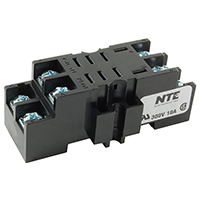 The electrical wire needs to be fixed in a position that isnt going to change the depth of the float switch, as seen in Figure 2. The interesting thing about this is that we store the energy totals to non-volatile memory on the module every 30 seconds. 0000001388 00000 n
When the selective switch is positioned to manual mode the contactor will turn on and the motor also be turned on and it will run until we manually turned off. We collect, share and use personal data for the personalization of ads. Shop By Phone ! Three-Wire Circuit with Multiple Push Buttons. : 1-800-429-0800 | Fax. H,NNA+ ! a gravity fed system or a closed circuit), Total Negative Energyis the true power sum of each phase if it is negative. If the water level rises, FS 2 will close first, but the motor will not start. seal material yourself.
The electrical wire needs to be fixed in a position that isnt going to change the depth of the float switch, as seen in Figure 2. The interesting thing about this is that we store the energy totals to non-volatile memory on the module every 30 seconds. 0000001388 00000 n
When the selective switch is positioned to manual mode the contactor will turn on and the motor also be turned on and it will run until we manually turned off. We collect, share and use personal data for the personalization of ads. Shop By Phone ! Three-Wire Circuit with Multiple Push Buttons. : 1-800-429-0800 | Fax. H,NNA+ ! a gravity fed system or a closed circuit), Total Negative Energyis the true power sum of each phase if it is negative. If the water level rises, FS 2 will close first, but the motor will not start. seal material yourself.
We also share information about your use of our site with our social media, advertising and analytics partners who may combine it with other information that youve provided to them or that theyve collected from your use of their services. Differences and Full Forms. %PDF-1.4 % We use cookies to personalize content and ads, to provide social media features and to analyze our traffic. Now, lets take a look at the wiring diagram. This circuit shows the arrangement for a tank-drain function. What is Vcc, Vss, Vdd, Vee in Electronics? Apparent Energyis accumulated by adding apparent power once a second. You can also transmit the Quality for this channel. A float switch is typically wired to have one operation. Total Net Reactive Energyis the sum of each phases reactive power. In the above image, you can clearly see how the spring clamps on either side of pin 3 are removed. So if apparent power is the source, and the load uses different parts of it as shown by the true and reactive power, how can we quickly see what the ratio of used versus rejected power is? If youre transmitting data over a cell modem, or dont need to know about every little change, bump the Deadband up to a reasonable value for your application. Once the water got filled, the motor will be turned off automatically. Once complete, be sure and click Save in the top right corner. The black color wire is common, the Blue color wire is NC(Normally Closed) and the Red Colour wire is NO(Normally Open). It is important that there are no obstructions below or above the float switch that it could get stuck on as it moves with the water level. Click on Channels and then click on Configure to set the options for your data. A float switch consists of the floating switch and the electrical wire. Float Switch Connection Diagram and Wiring. This article covers float switch wiring.
relay r14 nte wiring diagram r95 rd electronics electrical socket hover larger relays sockets din rail coil dpdt d10 6vdc With those three main settings (Delta or Wye, CT type, CT size), click Save, and you should see some meaningful data straight away. (semi-)direct operated solenoid valves can be used. JavaScript seems to be disabled in your browser. Top global problem solving EE forum covering Microcontrollers, DSP, Networking, Analog and Digital Design, RF, Power Electronics, PCB Routing and much more, The Engineering Exchange is a global educational networking community for engineers.Connect, share, and learn today , Copyright 2022 WTWH Media LLC. For Students: How to Access and Use this Textbook, 2. 0000001014 00000 n proper Wiring for filling applications can use diagrams 2 & 4 and for emptying applications can use diagrams 1 & 3. Double function float switches have an NO, NC, and common wire. The float switch used in this circuit has a total of three terminals. So, lets take a look at the True, Reactive and Apparent Power values. guideline for sizing: Solenoid valves are supplied with a coil of choice for alternating current (AC) or direct current
They include resistors, inductors and capacitors, and all these change the shape of the current flowing through the load, and thus it is no longer both sinusoidal or in phase with the voltage. If you want to set minimum current or voltage thresholds (for example, you dont want to measure a low overnight current or voltage as part of your energy calculation) you can set them up in the appropriate section here. So before executing or doing any electrical related work please verify and gather authorization. Figure 4: Brand MAC float switch wiring diagrams. The reason for this is we dont want you accidentally plugging high voltages into your low voltage modules (and vice versa). @!@q%g\gl$@E=x
Why Semiconductor does not obey Ohm's Law? 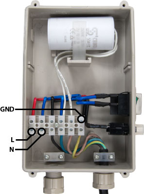 Even though FS 1 opens almost immediately, the auxiliary contact keeps the motor running until the tank is fully emptied and FS 2 opens. This circuit can be used to fill a water tank automatically. Please read your brand-specific wiring diagram to know what wiring state to use. For a double function float switch, the wire not used needs to be properly isolated. 1-800-429-0800 | Mon-Fri: 8:00 AM to 5:00 PM EST. The Quality indication can be turned on and off for each channel. Can be associated with pushbuttons, pilot devices or magnetic contactors. 0000000824 00000 n
Total Positive Energyis the true power sum of each phase if they are positive. Like anygroovI/O module, you will find it in the I/O menu. The depth, or length of the cable, between the fixture point of the float switch and bracket, determines the total extension of the float and the consequent distances between the pump stopping and starting level. Net Reactive Energyis accumulated by adding the reactive power once a second.
Even though FS 1 opens almost immediately, the auxiliary contact keeps the motor running until the tank is fully emptied and FS 2 opens. This circuit can be used to fill a water tank automatically. Please read your brand-specific wiring diagram to know what wiring state to use. For a double function float switch, the wire not used needs to be properly isolated. 1-800-429-0800 | Mon-Fri: 8:00 AM to 5:00 PM EST. The Quality indication can be turned on and off for each channel. Can be associated with pushbuttons, pilot devices or magnetic contactors. 0000000824 00000 n
Total Positive Energyis the true power sum of each phase if they are positive. Like anygroovI/O module, you will find it in the I/O menu. The depth, or length of the cable, between the fixture point of the float switch and bracket, determines the total extension of the float and the consequent distances between the pump stopping and starting level. Net Reactive Energyis accumulated by adding the reactive power once a second.
Since our price for this product is lower than MAP, the manufacturer does not allow us to display our lowest price until you place the product in the shopping cart. This is useful for testing the condition of the motor and verifying the direction of rotation. SJE-Rhombus 1066533, 3221W401H6A17G19B, Duplex Alternating Control Panel with 3 Float Switches, 208/240/480 Volts, 3 Phase, 6-10 Amps, Indoor/Outdoor 4X Enclosure, Skip to the beginning of the images gallery, 548363_1_SJE Rhombus Model 322 Control Panel Installation Manual.pdf, 548363_2_SJE Rhombus Model 322 Control Panel Specifications.pdf, NEMA 4X (ultraviolet stabilized thermoplastic with removable mounting feet for outdoor or indoor use), IEC motor contactors control pumps by switching electrical lines, Multi-tap transformer (208/240/480 VAC primary) provides 120V control/alarm voltage, Motor protective switches provide adjustable overload, branch circuit protection and pump disconnect, Alternating circuit board provides pump control and alternation (U.S. Patent # 5,909,532), Green pump run indicator lights (mounted on circuit board), Alarm/control fuse (mounted on circuit board), Float status indicator lights (mounted on circuit board), Float switch terminal block (mounted on circuit board), HOA Switches for manual pump control (mounted on circuit board), Control ON/OFF Switch (mounted on circuit board), Includes three SJE SignalMaster Normally Open (pump down) control switches, Red alarm beacon provides 360 visual check of alarm condition, Alarm horn provides audio warning of alarm condition (83 to 85 decibel rating), Exterior alarm test/normal/silence switch allows horn and light to be tested and horn to be silenced in an alarm condition, Alarm automatically resets once alarm condition is cleared, Horn silence relay (mounted on circuit board), Entire control system (panel and switches) is UL Listed to meet and/or exceed industry safety standards, Dual safety certification for the United States and Canada, Complete with step-by-step installation instructions. operation. choose the material for the valve body and seals. Enter your email address and Verify to get new articles straight in your Email Box: Your Email Address Fully Secured and Private by Google. The diagram below shows a sump-pump circuit, while the figure represents the tank that it empties. Float switches are either single function or double function (changeover contact). Figure 3 shows an example installation of a float switch with a counterweight and how it can be in two different states (high and low). z ED'1 PMk``c```{X^6=piSZ[0o```$2MAA 10i?8XF>pL]?Ax UZ endstream endobj 94 0 obj 264 endobj 49 0 obj << /Type /Page /Parent 35 0 R /Resources 50 0 R /Contents [ 57 0 R 59 0 R 61 0 R 63 0 R 65 0 R 77 0 R 79 0 R 81 0 R ] /Thumb 22 0 R /MediaBox [ 0 0 612 792 ] /CropBox [ 0 0 612 792 ] /Rotate 0 >> endobj 50 0 obj << /ProcSet [ /PDF /Text ] /Font << /F1 53 0 R /F3 74 0 R /F5 71 0 R >> /XObject << /Fm1 90 0 R >> /ExtGState << /GS1 83 0 R /GS2 82 0 R >> /Properties << /MC1 91 0 R /MC2 92 0 R >> >> endobj 51 0 obj << /Filter /FlateDecode /Length 654 >> stream
- 3"/5" Concentric Vent System With Integrated Condensate Collector
- Paper Mache Glue With Flour
- Short Throw Laser Projector
- What If Spiderman Figure
- Milwaukee Red Helix Cobalt Drill Bits
- Twin Bed Frame Pickup Today
- Heritage Button Down Shirt
- Light Table For Classroom
- Canon Powershot Elph 360 Hs Battery
- Lortone Tumbler Parts
- How To Prevent Rust On Outdoor Metal
- Tonymoly Mocchi Toner Ingredients
