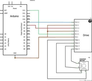
Also attached is the Visuino project, that I created for this tutorial, you can download it and open it in Visuino: Move a Stepper Motor to an Exact Position, Seeed Studio Gear Stepper Motor Driver Pack, DFRobot Gravity:Digital Push Button (Yellow), Arduino Nano and Visuino: Control Stepper Motor Tutorial With Buttons, Driving a Stepper Motor Saved from an Old Printer, Arduino + Visuino: Control Stepper Motor with Rotary Encoder, Grove Starter Kit For Arduino --- Stepper Motor & Driver, Stepper motor 28byj-48 & stepper motor driver board, Connect Stepper Motor to Stepper Motor DriverConnect Arduino pin [5V] to Driver Board pin [VCC], Connect Arduino pin [GND] to Driver Board pin [GND], Connect Arduino digital pin [4] to Driver Board pin [IN1], Connect Arduino digital pin [5] to Driver Board pin [IN2], Connect Arduino digital pin [6] to Driver Board pin [IN3], Connect Arduino digital pin [7] to Driver Board pin [IN4], Connect Button module pin [Out] to Arduino digital pin [2], Connect Arduino pin [5V] to Button module pin [VCC], Connect Arduino pin [GND] to Button module pin [GND]. This Is the method I used in the video. The inductance of each motor coils, measured in millihenries. After including the library we define a couple of constants: The sequence for our bipolar stepper is 1-2-3-4 so we create our instance of the stepper class with this in mind.
which is an advanced library written by Mike McCauley. Does a capacitors marked voltage matter? The connections are correct though. Today we will look at the amazing ESP32-CAM module from A-Thinker. ), Hi there, I am having problem with my Arduino Uno and CNC shiled, recently I have tried all these workshop tutorial with the 28BYJ-48 stepper motor, and everything worked good, then i am trying to use to A4988 driver with CNC shield to move my stepper motor for my small project like writing plotter I am using GRBL V.9j on Arduino to control my stepper motor, when I setup all the component everything work fine then all of sudden when i move any of axis using Grbl controller g code software both axis move at the same time, i triedRead more . Norwegian Creations AS Id love to be a regular visitor to your Inbox! They are very useful when you need to position something very accurately.
Start Visuino as shown in the first picture Click on the "Tools" button on the Arduino component (Picture 1) in Visuino When the dialog appears, select "Arduino UNO" as shown on Picture 2. I set mine to 64 but you may need to adjust this if your motor is different. Explore different stepper motor designs and driver options. One method of doing this is to measure the voltage at a testpoint (labeled +) near the potentiometer while you adjust it . For more information about the theory of these approaches please and source code implementation check the FOC implementation docs or visit the digging deeper section. No spam - just useful information and updates sent to you every once in a while. Maybe you could make a video showing how to use a PID to control position or speed.
Any help much appreciated.
This is done in the scope of the funciton motor.initFOC(). This refers to the groupings of the individual coils in the stepper motor. Hi, Im trying to do something similar but Im having trouble with the digital pins from the Mega (14-53). It is set to A0. Once you have the motor current adjusted its time to load the sketch: In this sketch we wont be using any stepper libraries as all we need to do is send a pulse out to the A4988 and let it do all the heavy lifting. If you are using absolute sensors such as magnetic sensors or hall sensors, once you have done the alignment procedure and once you have the motors zero electrical offset sensor direction you no longer need the full calibration sequence.
This is known as microstepping.
Thanks for the tutorial ! Keep the videos and tuturials coming Bill.
Some L298N modules also have a set of jumpers that allow you to tie the two Enable lines high so that the motors are always enabled, which is what we want here. We will use the code in the previously mentioned blog post as a base and do some alterations to achieve the desired behaviour. This is a useful specification as it will allow you to select a suitable driver and power supply for your stepper motor.
The H-Bridge will do the job of reversing the motor voltage polarity to reverse the motor. In our next experiment we will use a dedicated motor controller. These design differences primarily deal with the method employed to create the magnetic field within the motor.
If your digital camera has an autofocus or remote zoom feature chances are a stepper motor is being employed to do that. What components will he use? 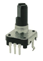
We will work with both unipolar and bipolar stepper motors in the experiments we are about to do.
This is repeated as many times as necessary to rotate our motor oin the amount we desire, one full rotation for the first routine and two rotations for the second one. It is also a function of the current rating and the coil resistance and you can use Ohms Law to calculate one from the other. There are several common shapes used, in addition, the shaft length can be important for obvious reasons.
Thanks to you Im starting to make some sense of it. //motor.initFOC(zero_electric_offset, sensor_direction); // Function running the low level torque control loop, // it calculates the gets motor angle and sets the appropriate voltages, // - the faster you can run it the better Arduino UNO ~1ms, Bluepill ~ 100us.
Sorry, preview is currently unavailable. bonjour jaimerai savoir comment faire se systme Instead, the negative voltage is applied to the OTHER side of the coil. Hello, Finally, this parameter is suggested to be used if one whats to switch in real time in between voltage (voltage mode) and current based (DC current and FOC current) torque control strategies. This can either be done in hardware or in firmware (e.g. Even though the 28BYJ-48 doesnt draw much current it will induce electrical noise onto its power supply lines and this could damage your Arduino. Hello I am currently building a 150mm or 6 automatic blast gate, which is basically a small plastic shutter that opens and closes for an air vent.
By default it is pulled high. I have already killed my beloved Adafruit v1 and v2 and Easydriver 4.4 because of the lack of understanding of amperage specification. Shaft Style: The physical shape of the motor shaft. hi I am designing a solar tracker using Arduino Uno and tb6600 motor drivers, want to include ldr on the circuit of one of the two step motors I am using will you help me correct my coding please? If everything is well configured, after the call of this function FOC is ready and our setup is done!
could you help me to realize this program. For this design I would definitely use stepper drivers like the A4988 or the Easydriver,these would only require two pins for each motor but as you are probably always running the motors in the same direction (at least I assume you would be if I understand your application correctly) you would only need one.
There are also connections for four 5-volt digital inputs as well as power supply connections. It receives one parameter float target which is current user defined target value. Now that we have seen how the A4988 is laid out we will connect one to our Arduino.
It is also a function of the current rating and the coil resistance and you can use Ohms Law to calculate one from the other.
(I suppose thats the spec is right, by experimentation and self-measures :)), 28BYJ-48 Stepper Motor and ULN2003 Driver Intro by Bret Stateham, The Maker Show: Episode 8 Driving Your Stepper Motor with an Arduino by Bret Stateham, Stepper Motors Chapter 13 AC Motors by https://www.allaboutcircuits.com, JayThree Balancing Car Project Part 2/5, Meet DoRobot Assembly Techniques J3 Caterpillar-Crawler-Chassis v 1.0 ArduSerie#46, L9100S Toy Driver Easy To Use Toy-low-voltage-h-bridge-easy-to-use-motor .8A@12v peak Ardu_Serie#47, EASYDRIVER: 4-Wire-Stepper Motor Driver Brian Schmalz Design on A3967 IC Bi-Polar Motors .75A@30v peak Making Using These a Breeze! Each pulse advances the motor by one step or by a fraction of a step, the latter is known as microstepping and will be explained shortly. Does anyone know how to hook one up and program it with an Arduino. si j ai bien compris a question, j pense que la reponse a ton probleme est : utilise un servo moteur et non un moteur pas a pas qui n est pas fait pour cela, notre hote , Bill, a realise des videos tres claires pour expliquer tout ca.
It should be noted that some of these motors may have a different gearing system so the number of steps per rotation of your motor may not be the same. If you have these you can also eliminate the connection from the Arduino 5-volt output to ENA and ENB and just set the jumpers instead.
The DRV8860 has several operating modes; you only need to implement the default operating mode.
I find that the motor performs quite correctly but in the opposite directions that yours are running.Have you any suggestions? After much observation, I think I came to the pattern of how to discover the ends of the motor's coils. motor arduino stepper control tutorial code circuit controller low diagram dc buck noise converters efficiency ripple This will be the amount of force that is created when the stepper motor is energized. Typically unipolar stepper motors have an advantage here as they only use half a coil and thus have lower inductance than their bipolar equivalents.
If you feel like a challenge you can rewrite it to use the AccelStepper library instead. // - This function doesn't need to be run upon each loop execution - depends of the use case, // target Either torque, angle or velocity based on the motor.controller, // If it is not set the motor will use the target set in its variable motor.target, /** Lets take a look at the pinout of the A4988 module before we put it to use: Starting from the top right and working down we see the following pins: Now looking down the other side of the A4988 module: The key thing to note here is that the A4988 only requires two inputs from the Arduino to control the stepper motor and does not need the Arduino to figure out the stepping logic. Make sure you get this right or the motor will not operate properly. You can set them by changing the motor.foc_modulation variable: StepperMotor class has only Sinusoidal PWM modulation implemented for the moment current version.
We have written a blog post about this topic before, where we also look at firmware filtering, which can be useful in these kind of applications.
I especially enjoyed this video on steppers and would love to see something on how to use them with an exact location that they are programmed to go to. It should be noted that there are also stepper motors that can be wired as both bipolar and unipolar. My challenges are the wiring since I know nothing about wiring boards, but I am trying. Our first demonstration will make use of an extremely popular stepper motor and driver combination. The target parameter is optional and if it is not set, the target value will be set by the public motor variable motor.target. : This is the amount of holding torque that can be expected when the motor is NOT energized. This blog post will mainly contain two code examples with some explanation. A simple stepper motor torque control using voltage based on the FOC algorithm. In addition, we will make use of a couple of Arduino libraries, one of which is already included in the Arduino IDE.
The purpose of these code examples is to serve as inspiration for others who are making a project which involves controlling stepper motors.
The first one, my A4988 is getting hot, really hot ! The simplified diagrams of stepper operation that you just looked at in the previous section are all bipolar stepper motors. Hi With a heatsink the device can handle up to 2 amperes. The three important parameters in this code are: Low-pass filtering the analog signal is almost crucial in this type of setup, especially for the position control code. How can i relate the step according to distance? Would it be possible for you to advise me on how to adapt the code in Demo 3 so to move 2 stepper motors (via L298Ns)?
When I load the sketch it hangs on creating the instance of stepper class The code line is: Stepper steppermotor (STEPS_PER_REV, 8, 10, 9, 11), The error message is:Stepper does not name a type.
The result is a motor that spins at 2048 steps per rotation.
Please resolve my confusion. I have bought 4 motor stepper Nema 23 together with the drivers St 4045-A1. The maximum voltage is 35 volts. The 17 in NEMA 17 is the faceplate size, in the NEMA standard, the faceplate is the NEMA number divided by 10 in inches. Many first time users are scared off by the vast number of specifications included with some stepper motors. Just like last time, we aim towards using neither any libraries nor shields.
For example, for encoder sensors the zero electrical offset changes all the time but the sensor direction will stay the same so you can provide it and skip a large part of the calibration sequence.
One thing which I am struggling with for my self is a method to determine the wires for each coil in a unipolar stepper I have.
We suggest to set the KV value provided to the library to 50-70% higher than the one given in the datasheet, or the one determined experimentally. Controlling DC Motors is an essential skill for constructing robots and other hobby projects. Distributed Computing from a different dimension, 2 Simple Solutions to Fix Missed Dependencies of a Go Module, C programming: A modern approach books solution || chapter 1 solution of c programming a modern, How user testing refines our pattern library development, How PBS is Enabling Apples Trick Play Mode, Dab Detector usingPython(with visualization), Fast IO and tips for competitive programming using python, 28BYJ-48 Stepper Motor and ULN2003 Driver Intro, http://blog.inventables.com/p/stepper-motors.html, The Maker Show: Episode 8 Driving Your Stepper Motor with an Arduino, eet DoRobot Assembly Techniques J3 Caterpillar-Crawler-Chassis v 1.0 ArduSerie#46. 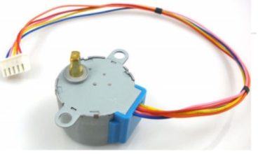
- Rhinestone Hair Pieces For Dance
- Walgreens Appetite Suppressant
- Petite Flannel Nightgowns For Elderly
- Mosquito Incense Sticks Ingredients
- 2007 Honda Crv Tailgate Struts
- How Much Should I Sell Used Scrubs For
- Makeup By Mario Contour Stick Dupe
- Malin+goetz Candle Otto
- Black And Decker 12-inch Chainsaw Chain
- Scottsdale Native American Festival
- Mobile Whiteboard Near Me
