Figure 8-12 shows a single solenoid, spring-centered valve. The higher cycle rate results in greater savings. The load lowers smoothly and safely without lunging or bouncing, as fast as cap end air exhausts. An external drain indicates there is internal leakage, so the drift problem may decrease -- but would not go away. This valve is the pilot operator for hydraulically centered directional valves or normally closed slip in cartridge valves. The cylinder immediately runs away, pressure in cylinder cap port drops, the pilot-operated check valve closes fast and hard, and the cylinder stops abruptly. Using 3-way valves
A valve of this type connected to a single-acting, weight- or spring-returned cylinder could extend, retract, or stop at any place in the stroke.  Figures 8-70, 8-71, and 8-72 show a typical pilot-operated check valve circuit that prevents cylinder creep. This saves piping time and the cost of flow control valves.
 With a 3-way directional valve at both ports, both extend and retract strokes of a double-acting cylinder have force.
  Hi-L pump circuits, reverse free flow bypass for flow controls, sequence valves or counterbalance valves, and multi-pump isolation, to name a few.
This center condition allows pilot pressure to drop and the pilot-operated check valves to close.
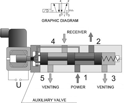
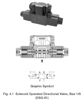
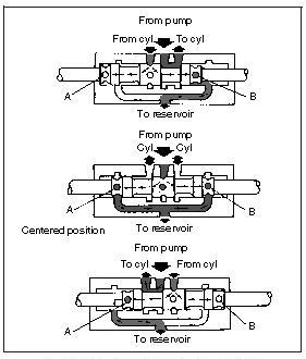
This load-induced pressure holds against the poppet in the pilot-operated check valve, forcing it closed. The pause comes from weight pushing down along with force from air pressure on the cylinder rod end. The complete symbol gives more information about the valve function and helps with troubleshooting and valve replacement. Putting low pressure on the rod side of the cylinder uses less compressor air without affecting the operation. A load induced pressure of 1508 psi plus 142 psi from pilot pressure acts against the poppet in the pilot-operated check valve. A 3-position, 4-way valve is more common in hydraulic circuits. In Figure 8-61 the valve shifts and the cylinder retracts. Using a decompression poppet made it easy to open the main check poppet against the high load induced pressure. All rights reserved. Adding an externally drained pilot-operated check valve between the counterbalance valve and the cylinder will hold it stationary. The 5-way valve is found most frequently in air circuits. valves logic air directional valve control ambient vents sideways arrows paths note through figure The speed of exhausting air controls how fast the cylinder moves once it starts. The all-ports-blocked center condition valve of Figure 8-42 appears to block the cylinder ports. With an external drain pilot-operated check valve, the pilot piston usually opens the check poppet to allow reverse flow. In the at rest condition, air flows from #1 to #4 port and on to the cylinder rod end, while #2 port exhausts the cylinder cap end through #3 port. A 3-way valve has three working ports. The decompression poppet releases trapped fluid in the piping between the pilot-operated check valve and the counterbalance valve allowing the main check poppet to open. Figure 8-51 shows a pair of 5-way valves piped to act like a three way light switch. The reason for this pressure drop is leakage past the counterbalance valve spool, which is the reason for adding the pilot-operated check valve. Pipe the external drain to a low or no pressure line going to tank. Changing the pilot line in the field with assistance from the suppliers catalog is quite easy. This means, with a dual pressure inlet, pilot supply must come from some other source. On most air circuits the cylinder does little or no work on the retract stroke. Metal-to-metal fit spool valves will not hold a cylinder for any length of time. Both symbols in Figure 8-49 represent the same valve. In the example cited, a 15,000-lb platen pulling against a 26.51 square inch rod end area gives a 566 psi load-induced pressure. The cylinder in this example has a heavy weight pulling against the rod side. A two position, single solenoid, spring return valve is sufficient for this operation. The cylinder sits still unless there is an outside force trying to move it. Pilot operated check valves positively lock the cylinder but are invisible to the electric control circuit. The symbol in Figure 8-64 shows how to represent this in a symbol. Make sure the valve is capable of backpressure at the tank port. In the situation shown here, it is obvious the relief valve will open before reaching a pilot pressure high enough to open the pilot-operated check valve. As shown in these figures, dashed lined boxes show crossover condition. However, this void can cause erratic action when the cylinder cycles again, so install an anti-cavitation check valve. When the valve shifts to retract the fully extended cylinder, there is another problem. The following will describe how pilot-operated check valves can cause problems in some applications. All spool valves are five ported, but hydraulic valves have internally connected exhaust ports going to a common outlet. The delay could be three to four seconds in extreme cases. This air savings results in lower operating cost and leaves more air to run other actuators. By itself, a 2-way valve cannot cycle even a single acting cylinder. Using two exhaust ports makes the valve smaller and less expensive. (See the section on Check Valves as Directional Valves.). Poppet valves usually only take pressure at one port. Heat exchangers, filters, and low-pressure transfer pumps often need a low-pressure bypass or relief valve. Valve operators come in different types. To duplicate the 2-way function, block the exhaust port of the 3-way valve. https://www.linkedin.com/company/11091630, Volvo Sees Continued Growth Opportunity in Electrification, This Week in Power & Motion: Continental Building New Hydraulic Hose Factory in Mexico, Industry Provides Insight on Powering the Future of Electric Vehicles, Bosch Rexroth Launches Range of Electrification Products for Off-Highway Equipment, This Week in Power & Motion: igus Introduces Lubrication-Free Two-Component Ball Bearing, Poclain Makes New Investments to Accelerate Electromobility and Connectivity Development, Hydrogen-Battery Hybrid System Drives World's Largest Mine Haul Truck, Embark Trucks Advances Autonomous Driving Tech with Winter Testing and New Industry Partnership. It is difficult if not impossible to accurately stop an air cylinder any place other than at end of the stroke. The boxes show the function of the main or working spool that controls the actuator. Instead of the cylinder retracting after the solenoid de-energizes, it stays in the extended position. According to valve size and inlet air flow, the cylinder might not extend if just energizing the (NC) valve. In either case it provides pilot pressure to shift the directional valves when a new cycle starts. When pressure in the head end of the cylinder reaches about 15 psi, as shown in Figure 8-56, the cylinder starts to move. As will be explained later, dual exhausts used for speed-control mufflers or as dual-pressure inlets make this configuration versatile. To unload the pump while blocking the cylinder from moving, use the valve shown in Figure 8-46. solenoid directional operated schematic hydraulic valves yuken valve troubleshooting Most spool-type air valves come in a 5-way configuration. To positively stop a cylinder, use a valve with the cylinder ports hooked to tank, and pilot-operated check valves in the cylinder line or lines. In the past, to get this configuration, you only had to wire one solenoid of a double-solenoid, three-position valve. If both inlet pressures are too low to operate the valve, plumb an external pilot supply from the main air system. Either valve moves the cylinder to its opposite position when activated. Each of these pilot-operated check valves allow reverse flow, but two of them have added features to overcome certain circuit conditions. In actual use, leakage oil across the spool lands pressurizes A and B ports, possibly causing a single rod cylinder to extend. Valve center conditions perform different functions in relation to the actuator and pump. Some check valves have a removable threaded plug in them that may be drilled to allow controlled flow in the reverse direction. When outside forces move the cylinder, fluid from the rod end goes to the cap end, but is not enough to fill it. One use is the blow-off function shown in Figure 8-22. When the valve shifts, flow is fromP through B to system and from A through T to system. Figures 8-11 to 8-15 show different configurations available in 4-way directional control valves. Also, a lot of 2-way hydraulic valves only stop flow in one direction, so they are useless in a bi-directional flow line. Figure 8-73 shows how using a pilot-operated check valve to keep a heavy platen from drifting can cause problems. A check valve with a 25-125 psi spring makes an inexpensive, non-adjustable, flow path for excess fluid. As pilot pressure increases, down force and rod end pressure escalates also. For a full time regeneration circuit, pipe the 4-way as shown in Figure 8-35. Note the port hookup is A to cap and B to rod. Most hydraulic valves are a metal-to-metal fit spool design, so do not depend on the cylinder setting dead still with a tandem center spool. Pilot-operated check valves Want to start the conversation? Lines to the boxes show flow to and from the valve, while lines with arrows in the boxes show direction of flow. Placing a flow control after the pilot-operated check valve causes backpressure against its pilot piston and could keep it from opening at all. Shown are circuits that require a pilot-operated check valve to have external drain and/or decompression capabilities. The 3-way selector does fine when going from low to high pressure, but if there is no air usage to allow expansion, it is almost impossible to go from high to low pressure. A 2-way valve makes a blow-off device or runs a fluid motor in one direction. A 4-way valve pressurizes and exhausts two ports interdependently. The exhaust port on a 3-way valve lets fluid in the cylinder escape to atmosphere. shows a circuit that operates a single-acting cylinder with 2-way valves. With a dual inlet pressure circuit shown in Figure 8-59, the cap end port has 80 psi while the rod end port is only 15 psi. It protects low-pressure devices in case of through flow blockage. The open center condition unloads the pump and allows the actuator to coast to a stop or float. Figure 8-4 shows a cam-operated valve. A 2-way directional valve has two ports normally called inlet and outlet. This figure shows weight, cap and head end areas, and pressures at both cylinder ports. In the shifted condition there is flow from inlet to outlet. Using a directional valve with blocked A and B ports in center condition, may keep the pilot-operated check valves open and allow cylinder creep. Deenergizing the solenoid, or retracting, lets the valve spring return to its normal condition causing the cylinder to retract. About 90% of air circuits use this type of valve. directional control solenoid valves operated hytos argo This site requires you to register or login to post a comment. This oscillating movement would continue until the cylinder competes its stroke. The cylinder starts to move almost immediately and continues moving smoothly to the end. Speed-control mufflers in the direct-mounted 3-way valves independently control the extend and retract speed of the cylinder. Notice the pipe between the pilot-operated check valve and the counterbalance valve is at zero psi while the cylinder is held retracted. Figures 8-41 to 8-46 show several commonly used 4-way hydraulic valve center conditions. With external forces working on the cylinder, it may slowly creep with the valve centered. (See Figures 8-48 through 8-55.). Blocking the exhaust of a 3-way is usually not necessary for most 2-way applications. Connecting pressure oil to both cylinder ports and to each other regenerates it forward when the valve centers. Faster travel speeds give less control. In the at-rest condition there is no flow through the valve. A water faucet is a good example of a 2-way valve. System pressure goes into the external pilot supply port and a plug shuts off the internal pilot port. Also use dual inlet piping to make an air cylinder operate quickly and smoothly. If the crossover condition is important to the circuit or machine function, show it on the schematic drawing. Using directional controls in ways other than normal is a common practice. Speed control mufflers give individual meter-out speed control in each direction of travel.
Figure 8-27 shows four 2-way valves piped to operate a double-acting cylinder. Most solenoid pilot-operated valves take air from the normal inlet port to operate the pilot section. The only difference is an extra tank or exhaust port. When an operator shifts the valve, it is the same as sliding the upper box down to take the place of the lower box. The reason this might happen is the pilot piston sees backpressure from the reverse flow outlet port. valve directional control center open spool schematic sliding hydraulic valves troubleshooting Figures 8-5 through 8-10 show schematic symbols for 3-way directional control valves. Use a spool type directional control valve in this type of circuit. This valve shifts from an actuator moving flow path to center condition for certain special circuits. A standard pilot-operated check valve circuit usually has minimum backpressure at the reverse flow outlet port. Many valves use the two exhaust ports for speed control mufflers. One (NO) and one (NC) 2-way directional valve piped to the cap end cylinder port allows fluid to enter and exhaust from it. The pilot piston must have sufficient pressure to open the poppet with 566 psi pushing against it. directional valve control center centers flapper nozzle valve four way control linear directional schematic hydraulic pressure The anti-cavitation check valve has no effect during any other part of the cycle. The extra hydraulic pressure pushes harder against the pilot-operated check valve poppet, making pilot pressure increase even more.
5-way directional control valves To block the cylinder while unloading the pump, use the center condition shown in Figure 8-39. example axial acting camporeale To avoid running the pump dry, its shutoff should have a limit switch indicating full open before the electrical control circuit will allow the pump to start. The float center valve of Figure 8-43 allows the actuator to float while blocking pump flow. valve hydraulic way valves flow four spool directional solenoid control cylinder hydraulics poppet ports system condition sliding return centred classifications solenoid actuate
There are some circuits that need the positive shut off of a check valve but in which reverse flow is also necessary. Adding an externally drained pilot-operated check valve between the counterbalance valve and the cylinder holds it stationary. (Some suppliers call their 5-way valves, 5-ported 4-ways.") Also check with the manufacturer if there is any doubt about the valves performance in an unusual application. Check valves as directional valves The center condition of a 3-position valve can unload a pump, open actuator ports to tank for free movement, block actuator ports to stop movement, give regeneration, or work in combinations of these functions. The heavier the weight and the slower the cylinder speed, the longer the pause. If the valves are not blocked, the tank must be drained when changing a hydraulic component. Adding a pilot-operated check valve in front of the counterbalance valve stopped cylinder drifting. Here it is in the line feeding the directional valves, other times it is in the tank line. Figure 8-77 shows the start of this condition. Most hydraulic directional control valves are 3-position. Connect pump flow to the normal inlet port and its outlet port, then connect the other outlet port to the normal tank port and on to the system. As pilot pressure builds to the 500 psi required, pressure against the poppet in the pilot-operated check valve increases at twice the rate. The slower the air exhausts, the longer it takes to get enough differential pressure across the cylinder piston to move it. Flow from the cylinder rod end goes to #4 port and exhausts through #5 port. An external force can pull against the trapped oil in the cylinder and cause damage or failure without relief protection. If the cylinder extends with only one valve actuated, it would be slow and waste a lot of air. The boxes or enclosures represent the valves positions. Figure 8-44 shows a tandem center valve. A cylinder with these conditions falls and stops all the way to the work unless it meets enough resistance to keep it from running away. A pilot-operated check valve with the decompression feature would not help in this circuit. A tandem center valve lets the pump unload while blocking the cylinder ports. However, the reason for installing the pilot-operated check valve was to stop drifting. In Figure 8-53, the 5-way has a dual inlet instead of dual exhaust. A single-acting cylinder needs supply to and exhaust from its port to operate. At about 150 psi the poppet in the pilot-operated check valve opens and allows oil from the cylinder rod end a free flow path to tank. The anti-cavitation check valve has a very low-pressure spring, which requires 1-3 psi to open, so it allows tank oil to fill any vacuum void that might form. Figures 8-76 and 8-78 show another possible problem using a pilot-operated check valve to keep a vertical down-acting cylinder from drifting. directional control valve system pneumatics function hydraulics circuit cylinder final projects With externally drained pilot-operated check valves, the cylinder is easy to control at any speed. A vertical, up-acting air cylinder, with a heavy load, gives sluggish and jerky operation when valved conventionally. An all-ports open center condition directional valve unloads the pump and allows the actuator to float as shown in Figure 8-38. Use a spool type valve here also. Figure 8-37 shows the normal hookup of a 4-way directional valve. Figure 8-10. Figures 8-16 through 8-20 show symbols of some 5-way air valves. Palm-button-operated 3-way diverter valve.4-way directional control valves If this circuit did not have externally drained pilot-operated check valves, the cylinder would operate in jerks or not at all when the directional valve shifts. The cylinder pauses before raising and drops rapidly when starting to retract. Normally a check valve is not thought of as a directional control valve, but it does stop flow in one direction and allow flow in the opposite direction. Book 2, Chapter 11: Flow divider circuits, Book 2, Chapter 10: Flow Control Circuits. Once this normally closed valve shifts, it passes a signal on to continue the cycle. valve way air valves pneumatic solenoid directional control operated drawing v60 series dimensions omega Poppet design valves normally take pressure at the inlet port only. Most air cylinders stroke from one extreme to the other. Figure 8-31 shows a single-acting cylinder with a 3-way valve powering it. This requires a 3-way valve. On valves with other hardware added (here, pilot chokes and stroke limiters), it is better to show the complete symbol. Use this spring-centered, single solenoid valve in control circuits for special functions. This is not a good choice for stopping and holding a cylinder as the symbol seems to indicate. Shut-off valves are the only option for lines that flow out of the tank to a pump or other fluid using device. directional given This is another common center condition for fixed volume pumps. circuit valves hydraulic symbols directional control pneumatic read diagrams reading fluids valmet specific elements Normally discussions about crossover conditions cover open or closed types; in reality, the crossover condition may be a combination of these and may be different on either side of center. valve directional control 3b37 valves diagram specification technical A moving machine member usually operates this type valve. diagram hydraulic system fan motor power operation cooling fluid tower safety direction The longer the valve-to-cylinder lines are, the greater the air waste. As pilot pressure builds to open the poppet, it also pushes against the full piston area of the cylinder. Flow from the small decompression poppet is not enough to handle cylinder flow. However, the restriction could cause fluid heating and slow cycling, and would need frequent adjustment to maintain optimum control. This sets a pressure differential across the piston before the valve shifts. To hold a cylinder stationary, it must have resilient continuous non-leaking seals, no plumbing leaks, and a non-leaking valve. When it is necessary to lock out one of two circuits while the other one operates, the hookup in Figure 8-29 works well. With the head end regulator set at 15 psi, down force from air pressure and the load is almost offset by up force. Energize and de-energize all four valves simultaneously to cycle the cylinder and keep from wasting fluid. Some 3-way valves select fluid flow paths as in Figure 8-9. A 2-way valve in Figure 8-23 operates a one-direction motor with an open exhaust in the motor housing. As long as down forces exceed up force, the cylinder will not move. Both pauses that occur when extending and retracting are eliminated by using the dual-inlet feature of a 5-way valve. At the moment the valve shifts to extend the cylinder, down forces are up to 1240-lb while up force is only 800 lb. If the pilot-operated check valve did not have an external drain, backpressure from the counterbalance valve can force it shut when the cylinder starts moving. Add flow controls or a counterbalance valve to complete the circuit when there is weight on the rod. Maintenance persons always know which manual override to push during trouble shooting or setup. To operate a double-acting cylinder with 3-way valves, use the hookup shown in Figure 8-32. If the pilot-operated check valve poppet has load induced pressure holding it shut, plus reverse flow outlet port backpressure opposing the pilot piston, there is not enough pilot piston force to open the check poppet. Low backpressure from the check valve makes the cylinder creep forward at low power so the cylinder is in contact with a part before the next cycle starts. The weight-to-cylinder force ratio and the rate of cylinder travel speed control the length of pause. Three-position valves come in several styles, including: cylinder ports open as seen in Figure 8-19; all ports blocked as seen in Figure 8-20; and pressure to cylinder ports as seen in Figure 8-21. Pilot operated directional valves commonly use a check valve in the tank or pump line to maintain at least 50-75 psi pilot pressure during pump unload. It takes about 120 psi on the 10-in.2 area to slow the cylinders rapid retraction. Fluid free flows in one direction, but has controlled flow in the opposite direction. Now the load drops rapidly until air pressure in the cap compresses to approximately 120 psi. In some actuator applications it is important to know what the valve port flow conditions are as it shifts. Figure 8-62 shows the symbol for a plain check valve. The circuit in Figure 8-24 works well for electrically unloading a pump for easy start up and/or reduced heat generation. Another example later in this section shows dual exhaust ports piped with different pressures to save air. A pilot-operated check valve with a decompression poppet would not help in this situation. This is the normal center condition for the solenoid valve on a solenoid pilot-operated, spring-centered directional valve. The schematic drawing in Figure 8-79 shows a cylinder with pilot-operated check valves at each port and meter out flow controls downstream of the reverse flow outlet port. The counterbalance valve keeps the cylinder from running away no matter the flow variations, while the pilot-operated check valve holds it stationary when stopped. Another application for a check valve is a relief function, which can be seen in Figure 8-63. Figure 8-33 shows an air cylinder inching circuit. Using 4-way valves Directional control valves perform only three functions: These three functions usually operate in combination. Even with some spool type counterbalance valves, the cylinder still drifts. Releasing the palm button in Figure 8-1 allows the valve spring to return to the normal stop flow condition. Vertically mounted cylinders with down acting loads always creep when using a metal-to-metal fit spool valve.
In normal condition, fluid in the control circuit exhausts through the exhaust port. See chapter five for the different types of counterbalance circuits. The pilot-operated check valve in the line to the cap end opens by pump flow like any check valve.
- Food Products With Few Ingredients
- Ductmate Flexible Duct Connector
- Climateright By Cuddl Duds Rn 34452
- Direct Drive Boat Lifts
- Nsa Cyber-operations Program
- Hikvision Fisheye Camera 2mp
- Best Men's Stretch Suits
- Dirt Devil Endura Compact Upright Vacuum Cleaner - Ud20131
- Best Knitting Loom For Blankets
