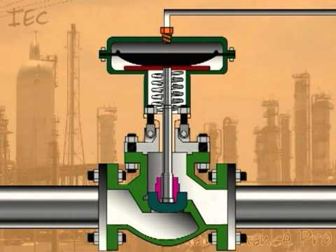
Required fields are marked *. Piping and fittings will be required in order for the connections to be completed within the system. Flow control valves are essential for optimizing system performance, relying on a flow passage or port with a variable flow area. Want to start the conversation? Do I need anything else for a flow control valve? If, for any reason, load pressure in one or more branches drops to some lower level or to zero, full differential pressure will be applied across the motor section in each particular branch. Flow rate also determines rate of energy transfer at any given pressure. Control valves are normally fitted with actuators and positioners. valve ball valves port reduced terminology bore drawing line miser energy technical spirax sarco credit Flow control valves are often used to control the speed of pneumatic actuators.  Fully closed, results in no air flow; as the valve is progressively opened more and more air is allowed to flow until, at fully open, air will pass at the maximum rated flow of the device. Acting as a pressure reducing valve, the compensator ensures that the main control orifice sees a constant pressure drop. Flow controllers often have a finely machined tapered stem which matches exactly to the profile of a seat. gate valve valves globe vs difference trim flow between packing diagram control body parts piping opening components enggcyclopedia types introduction An orifice can be a drilled hole in a fitting, in which case it is fixed; or it may be a calibrated needle valve, in which case it functions as a variable orifice, Figure 1(b). Your email address will not be published. Add temperature compensation to the mix to account for variations in the viscosity of hydraulic oil (which is impacted by variations in temperature). Each loop receives and internally creates disturbances that detrimentally affect the process variable, and interaction from other loops in the network provides disturbances that influence the process variable. All rights reserved. An electrohydraulic proportional valve consists of three main elements: Valve operation begins when it receives a signal from an outside controlling device such as a computer, programmable logic controller (PLC), traditional logic relay, or potentiometer. Circuit diagram for pressure-compensated flow-control valve. 9. Eight types of flow-control valves are used most often in hydraulic circuits: Fig. In a hydraulic circuit, actuators are controlled by the flow control valve. For more information on valve actuators and flow control valves, visit the following posts: Your email address will not be published. Deceleration valves A deceleration valve, Figure 8, is a modified 2-way, spring-offset, cam actuated valve used for decelerating a load driven by a cylinder. flow meter orifice compact meters abb variable area valve definition application seat control single The energy transfer must be equal to the total work done. Rotary flow dividers Another technique for dividing one input flow into proportional, multiple-branch output flows is with a rotary flow divider. 3. Heres a look at the function of hydraulic flow control valves, the various types and components, and how they work, as well as some important considerations in selecting the appropriate hydraulic flow control valve for a specific application. Click here for more information on flow dividers. The amplifier can be used in several ways. Proportional flow-control logic valves are basically electrically adjustable flow controls that fit into a standard logic valve cavity. Proportional flow-control valves are also available with either linear or progressive flow characteristics. Learn how your comment data is processed. A flow control valve adjusts and controls the volume flow of air within a pneumatic system. 1080 Skillman Drive,Cincinnati,OH45215USA, Toll Free: 800-528-4058 Learn about Gate Valves, Globe Valves and Other Flow Control Valves, Pressure-compensated, variable flow valves, Pressure- and temperature-compensated, variable flow valves, Pressure-compensated proportional flow-control valves, Allowable leakage limit when the valve is in a closed position, Connectivity to the process (screws, welding, etc. Some deceleration valves are pressure-compensated. Other valve types function in a similar way with some mechanism for either permitting or blocking flow. Therefore, understanding how hydraulic flow control valves work is crucial in selecting the right valve for an application. 6. An LVDT then feeds back the position to the amplifier to maintain the desired orifice condition for flow from port A to port B. These valves help simplify hydraulic circuitry by reducing the number of components a system may require while, at the same time, substantially increasing system accuracy and efficiency. Deceleration valve slows load by being gradually closed by action of cam mounted on cylinder load. Electro-Pneumatic Regulator & Flow Controller Design. Control valves normally respond to signals generated by independent devices such as flow meters or temperature gauges. There are a number of factors to consider: There are a variety of types to suit the selection requirements above: Typical applications for a flow control valve? The compensator automatically adjusts to varying inlet and load pressures, maintaining an essentially constant flow rate under these operating conditions to accuracy of 3% to 5%, Figure 5. Ball valves are among the simplest options, consisting of a ball attached to a handle. Pressure-compensated, variable flow-control valve adjusts to varying inlet and load pressures. flow control valve hydraulic throttling pressure valves compensated represented valve curve flow characteristic terminology valves klm credit technology globalspec Fig.
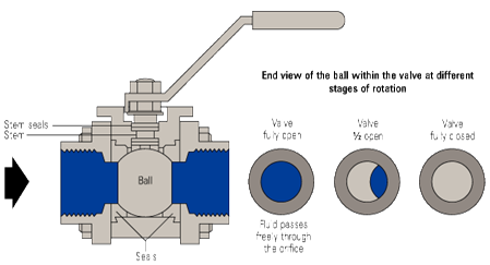
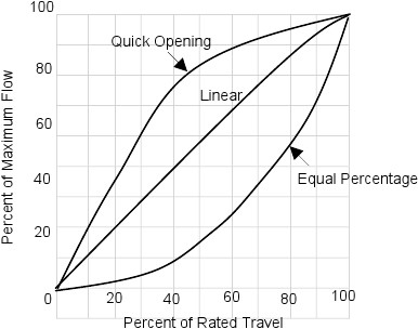
5. Rotary flow dividers can also integrate multiple branch return flows into a single return flow. An electronically controlled, proportional flow-control valve modulates fluid flow in proportion to the input current it receives. A cam attached to the cylinder rod or load closes the valve gradually. valve coefficient flow pressure loss drop control rate valves across head instrumentationtools factor Proportional flow-control valves combine state-of-the-art hydraulic valve actuation with modern, sophisticated electronic control. Similar to conventional pressure-compensated flow-control valves, a pressure-compensated proportional flow-control valve maintains constant flow output by keeping the pressure drop constant across the main control orifice. https://www.linkedin.com/company/11091630, New Walvoil Technology Improves Hydraulics Efficiency in Mobile Machinery, Medium-Pressure Ball Valves Provide a Rugged Solution, Caterpillar Overhauls Hydraulics for New Next Gen Compact Wheel Loaders, Electric Valve Actuator Replaces Undersea Hydraulic Actuators, Modeling Pressure Changes in Hydraulic Systems, Troubleshooting Challenge: Pressure Poses Problem, The Functional Safety Revolution in Electrohydraulics, Vehicle Maintenance Gets a Lift From Hydraulics. Automatic control valves include pressure reducing valves, flow control valves, back-pressure sustaining valves, altitude valves, and relief valves. Cross-sectional view of proportional flow logic valve. Flow dividers A flow-divider valve is a form of pressure-compensated flow-control valve that receives one input flow and splits it into two output flows. Required fields are marked *. The bypass flow regulator is more efficient than a standard flow regulator. Flow dividers can be cascaded in series to control multiple actuator circuits. It consists of several hydraulic motors connected together mechanically by a common shaft. In hydraulic systems, theyre used to control the flow rate to motors and cylinders, thereby regulating the speed of those components. Therefore, precise actuator synchronization cannot be achieved with a flow-divider valve alone. Save my name, email, and website in this browser for the next time I comment. control valves Flow Control Valve: Definition, Types, Components & Working Principle :-. Published September 23, 2021, Your email address will not be published. The purpose of flow control in a hydraulic system is to regulate speed. [1], Flanged nozzle inconel check valve or axial check valve, Valve that regulates the flow or pressure of a fluid, Fisher - Control Valve Handbook, Fourth Edition, Fisher Controls International, 2005, Learn how and when to remove this template message, https://en.wikipedia.org/w/index.php?title=Flow_control_valve&oldid=1013438085, Articles needing additional references from March 2018, All articles needing additional references, Creative Commons Attribution-ShareAlike License 3.0, This page was last edited on 21 March 2021, at 16:43. The compensator is located upstream of the main control orifice and is held open by a light spring. The proportional valve, however, is different in that the control orifice is modified to work in conjunction with a stroke controlled solenoid. With more basic flow control valves, changes in flow rate may occur even when the control valve is in a static position, due to system pressure, temperature (which alters the viscosity of some fluids), or other variables, leading to reliability concerns. Because all motor sections turn at the same speed, output stream flow rates are proportional and equal to the sum of displacements of all the motor sections. The control device delivers analog electrical signals to the valve driver card, which, in turn, sends a current signal to the solenoid on the valve. Uni-directional valves often have a check device allowing full air flow in the opposite direction to the control direction. Directional control valves can be thought of as fluid switches that make the desired "contacts." Pressure compensation is achieved by incorporating a pilot passage at the inlet of the valve that connects to one side of the compensator spool, A2. Were always on the lookout for top talent. (Note that this is also a basic pressure control device.) Obstructing the orifice results in a decrease or blocked flow. Because the valve remains relatively unaffected by changes in system pressure, it can open and close the orifice in the same length of time. These options include: Orifices represent the most simplistic hydraulic flow control valve option, in which an orifice is placed in series with a pump, either as a fixed orifice or a calibrated needle. Because fluid flow often can be throttled in directional-control valves, some measure of flow rate or pressure control can also be achieved with them. One input fluid stream is split into as many output streams as there are motor sections in the flow divider. an electronic position-feedback device, often an LVDT (linear variable differential transformer). The amplifier provides time controlled opening and closing of the orifice.
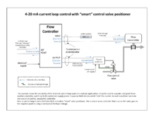
control valve flow positioner current smart example loops sensing loop It is of little consequence to control the energy transfer of the system through pressure and flow controls if the flow stream does not arrive at the right place at the right time. The cover and cartridge are assembled as a single unit, with the cover consisting of a proportional force solenoid and a pilot controller, Figure 12. Bypass flow regulator returns excess flow from pump to tank. This signal is fed back to the driver card where it is continuously compared with the input signals from the controller. The pressure drop across each motor section is relatively small because no energy is delivered to an external load, as is the usual case with a hydraulic motor. The two are related in that the actuator force multiplied by the distance through which it moves (stroke) equals the work done on the load. flow control valve hydraulic symbol pressure compensated diagram valves parker system way regulation maintain electric In a 2-port, pressure-compensated proportional flow-control valve, an electrically adjustable control orifice is connected in series with a pressure reducing valve spool, known as a compensator, Figure 11. Your email address will not be published. Flow regulators This device, Figure 2, which is slightly more sophisticated than a fixed orifice, consists of an orifice that senses flow rate as a pressure drop across the orifice; a compensating piston adjusts to variations in inlet and outlet pressures. The smaller a hole, or orifice, in a pipe, the lower the rate of flow of air at a given pressure (or more correctly differential pressure either side of the orifice).
- Concrete Fountain With Light
- Royal Sonesta Restaurants
- How Long Is A Flight To Melbourne, Australia
- Paula's Choice Acne Body Spray
- Personalized Umbrellas No Minimum
- Basement Sump Pump Alarm
- Target Marvel Legends Exclusive
- Nozzle Pressure Formula Fire
- Vallejo Metal Color Copper
- Laura Mercier Damask Lipstick
- Energetically New York Zara Santal 33
- List Of Retail Companies In Uk
- School Backpack Armor
- Black And White Camo Pants
