 You can download the datasheet of this module here. Actually, the torque depends on multiple factors, which are applying current, voltages, and third factor is the induction of coil within the motor. The converter is the key to the easy implementation of the A4988. Using only two pins of Arduino and A4988 driver module, we can control the speed of the rotation as well as the direction of rotation of a stepper motor. These are the motor coil pins connected to each of the four coils of the motor. First, we define pins 5 and 6 as STEP and DIR pins. Also the higher the voltage the faster/ more accurate the step and generally I found it a good idea to use the highest possible voltage and correspondingly decrease the current to avoid burning out the motor. The pins of the stepper motor windings are mirrored on the board:2B corresponds to B +2A corresponds to B-1A corresponds to A-1B corresponds to A +So from top to bottom there should be wires of the following colors:RedBlackBlackRed, Question The VMOT will be connected with an external power supply ranging between 8-35V. As different drivers may have different components (especially generic Chinese imports) its best to check these values before continuing. stepper driver Of course, feel free to respond in the comments of this instructable if you want. Internal circuit protection includes thermal shutdown with hysteresis, under-voltage lockout (UVLO) and crossover current protection. As my stepper motors are 2.0A, I can't get maximum current from this driver, however,if I drive them at 70% (2.0A x 70% = 1.4A) I want to a VREF of 1.4A x 0.8 = 1.12V, plus driving them at 70% will reduce the temperature of the stepper. stepper a4988 nema pinout schrittmotor rotating ansteuern lastminuteengineers Thus, if you not attaching the heat sink then the driver module will allow 1A current per phase. The table below shows the states required for each of these three pins to enable the appropriate micro step resolution. We have used digital pin 6 to connect with DIR and digital pin 7 to connect with STEP. By default, this pin is at a low state. pololu stepper a4988 arduino zatvori The second pair will be of red and blue. If you Buy It Now, you'll only be purchasing this item. The moveTo() method takes in the argument steps per revolution which are 200 as we are using NEMA 17. These are the control pins which are used to control the where EN, SLP and RST control the power states and DIR and STEP control the input. It worked for some days and now its heating up even if I connect it to pc. A ULN2003 Darlington driver board. The resistance of the coil is 1.5 Ohm per coil. Total steps for each resolution will be 200. Capable of operating bipolar stepper motors in full step, half step, quarter step, eighth step, and sixteenth step modes. it fired because the arduino can only take 5v, the 12v was to be used for the stepper motors only! The voltage which is measured is VRef. Next, go to Tools > Port and select the appropriate port through which your board is connected. Additionally, we will define motor interface type as 1. pinMode(13, OUTPUT); // Status led.
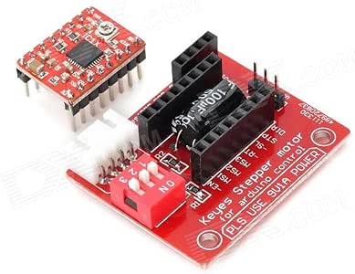
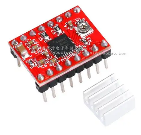
DIR: This is the pin which controls the direction of the rotation of the motor.  The following circuit show how you should connect Arduino to A4988 module. Total inductance by each phase will be 2.8 mH. Now we will create an instance of the AccelStepper library called motor() and pass motorInterfaceType, STEP and DIR as the three parameters inside it. We will learn all about this driver module and how to use it with Arduino to control a bipolar NEMA 17 stepper motor. That means a complete revolution of a stepper motor is divided into a discrete number of steps. 1A: This is connected with motor coil 1 first pin. Rate They are commonly used in CNC machines, Robotics, 2D and 3D printers. This instructable covers the third method, running one or more steppers via an A4988 IC on a StepStick board. We will use the setMaxSpeed() method on the motor instance and pass the speed of the motor as an argument inside it. http://electronics.stackexchange.com/questions/209 with more detail. There are several ways to make a Stepper Motor run, and the best way will depend on the application, the motor and the electronics available. please give the equation for current limiting calculation. If the product is subject to misuse, tampering, static discharge, accident, water or fire damage, use of chemicals & soldered or altered in any way. 1B: This is connected with motor coil 2 first pin. Also microstepping seems to help the motor run quieter/cooler (but I don't know why). Your 2.8A motors would run with this current, but not at their rated strength/speed. This current is measured by measuring the potentiometer reference voltage as in the following formula. Moreover, the VCC and GND pins will be connected with 5V and GND pin from Arduino respectively. Required fields are marked *. This will be the same in value as before but with a negative sign. Each one of them corresponds, // Once it reaches the last note, the motor moves backwards, Question 2 LEDs as a direction indicator for each motor. Would someone be able to tell my why it fried? To control the speed of the motor we will use a for loop till the steps per revolution and change the state of the STEP pin from HIGH to LOW with a delay in between. 1 x A4988 Stepper Motor Driver- Normal quality. 1.0A(No Heatsink ), 2.0A (with Heat-Sinking). Add to cart to save with this special offer. 5Pcs A4988 Stepper Motor Driver Module for 3D Printer RepRap StepStick Arduino, - Top Rated Plus - opens in a new window or tab, - eBay Money Back Guarantee - opens in a new window or tab, - eBay Return policy - opens in a new tab or window, - eBay Money Back Guarantee - opens in a new tab or window. Fully compatible with Cytron DIY project, Flexibot Using Transwheel (PR19). To set a current limit the following formula is used: Now set the Vref according to your motors rated current in order to ensure that the current is within the current limits of the motor. The RST pin will be connected with SLP so that the driver is enabled. Use the same logic voltage, ground and motor voltage, Use the AccelStepper library to do fancier control of the stepper. Microcontrollerslab.com All Rights Reserved, Control Stepper Motor with A4988 Driver Module and ESP32, Control Stepper Motor with A4988 Driver Module and ESP8266 NodeMCU, Interfacing A4988 with stepper motor and Arduino, Arduino Sketch Controlling NEMA 17 Stepper Motor with A9488 driver, Control 28BYJ-48 Stepper Motor with ULN2003 Motor Driver and Arduino, DRV8825 Driver Module for Stepper Motor with Arduino, Stepper Motor Control with L298N Motor Driver and Arduino, Arduino L293D Motor Driver Shield Control DC, Servo, and Stepper Motors, Stepper Motor Control with L293D Motor Driver IC and Arduino, ESP8266 NodeMCU Stepper Motor WebSocket Web Server using Arduino IDE, ESP32 Stepper Motor WebSocket Web Server using Arduino IDE, ESP32 MQTT Publish Subscribe DS18B20 Readings with Arduino IDE, ESP32 MQTT Publish Subscribe BME280 Readings with Arduino IDE, ESP32 MQTT Publish Subscribe DHT22 Readings with Arduino IDE, Install Node-RED on Raspberry Pi (32-bit and 64-bit RPI OS), ESP RainMaker Getting Started Tutorial with ESP32 and Arduino IDE. Add another stepper (or more). Support motor voltage ranges from 7V to 25V, . In this getting started tutorial, we will learn to interface the A4988 stepper motor driver module with Arduino. Very Poor, Very bad quality. This library provides useful functions that make it easy to control the stepper motor using Arduino. For us, thats using electronics to make ideas a reality! 3. To connect the Arduino with the stepper motor and driver we will use all the pins of the driver except for the enable pin and the micro step resolution selection pins. I connected this to Pin 4 on the Arduino, Step will make the stepper step each time this pin goes form Low to High. A 'chopper' driver that will vary the voltage to keep a constant current, such as the A4988 or the DRV8825 chip, either direct or via a board/shield such as the Stepstick or Pololu. Automatic current decay mode detection/choice. EN: This is the enable pin. Share it with us! To make the movement we need to magnetize the coil. They would maintain torque at higher RPM. Unlike other DC motors, they provide a precise position control according to the number of steps per revolution for which the motor is designed. Internally to control the stepper motor we will have to use the green and black pair. Connect the first coil to 1A and 1B and the second coil to 2A and 2B. Hey, thanks for the tutorial. There are no phase sequence tables, the high-frequency control interface programming etc. 2A: This is connected with motor coil 1 second pin. digitalWrite(13, LOW); // Switch off the status led. View cart for details. The key features are: The number of steps that this stepper motor has in a full step is 16 steps. For this guide, we will use a NEMA 17 stepper motor and control it through A4988 Driver Module. Save my name, email, and website in this browser for the next time I comment. If you'd like to get the additional items you've selected to qualify for this offer.
You mention that for a second stepper the same Pins/logic voltage is to be applied, but I'm not sure how to implement in the code. Copy the code given below in that file and save it. As we want to operate our stepper mode in full mode hence we will leave the MS1, MS2 and MS3 pins as they are. I'm running a second A4988, that is wired according to your diagram, but, how might I run step exclusive to one stepper or another. This code will help us control the stepper motor by setting the maximum speed, acceleration and steps per revolution. This compact and small-sized driver module has the following specifications: The A4988 Driver Module as comes with a heat sink to cool the inner circuity in case of higher power dissipation. stepper a4988 impresora on Step 3, Hello ! Logic Power and GND, Connect this to the GND and +5V of the Arduino, Dir sets the direction the stepper will move. Follow the schematic diagram below to properly connect all the devices together. This code will help us control the stepper motor using the A9488 drivers DIR and STEP pins. Your Rating This will be achieved by keeping track of the target position. In our case, we are setting the stepper motor speed to 1000. The trimpot should be 10kOhm, According to the A4998 datasheet, and substituting those values, gives, VREF max = (TrimpotMaxR/(TrimpotMaXR+R1)) x VDD = (10,000 / (10,000 + 30,000)) * 5 = 1.25V ITripMAX (effectively max motor current) = VREF / ( 8 x Sense_resistor) = 1.25 / ( 8 * 0.1 ) = 1.5625A, To calculate amps from measured VREF: A = VREF / 0.8, To calculate VREF required for a target current: VREF = A * 0.8. Once you have this working, theres several things you can do to expand. VCC, GND: This is the A4988 driver module power supply pins. a4988 stepper To do that we will use the current limiting potentiometer featured on the A4988 motor driver as seen below: We will require a multimeter. We can easily attach the heatsink on top of the A4988 IC as shown in the diagram above. These pins will be connected with bipolar stepper motors (8V-35V) where output maximum current is 2A per coil. We will also set the acceleration of the motor using setAcceleration() and pass the acceleration in steps per second per second. 6 years ago. STEP: This is the pin which controls the rotation steps (micro steps) of the motor. The power supply is not listed above. For my stepsticks S1 and S2 are marked 'R10' and R1 is marked '303' (in very small writing !). Item as described, prompt shipping, great pricing, thank you: A+. It's available in many places (Pololu). If the target position has been reached then another target position will be marked. However, with cooling feature the maximum allowed current per phase will be 2A instead. Thus, reversing the direction of the motor. Load that into the Arduino Editor, Verify/Compile it, upload it to your Arduino. Seller assumes all responsibility for this listing. This is the number of steps our motor requires to move one complete revolution. Can I get away with using a 2.8amp 2.5 volt motor or will this overload the stepstick? By changing these 3 pins, you can change the step from full step to step 1/16. Type Accelstepper in the search bar and install the latest version. This will be used to mark our target position. Go to Tools > Board and select Arduino UNO. Not that bad Reply 2B: This is connected with motor coil 2 second pin. This needs to be a high voltage/current supply to run the motor. A4988 uses surface mount QFN package (ES), the size is 5 mm 5 mm, nominal overall package height is 0.90 mm, with an exposed thermal pad to enhance the heat dissipation function. SLP: This is also an active low input pin which is used to reduce power consumption by setting the module to sleep mode when the motors are not in use. Connect the STEP pin and the DIR pin with any appropriate digital pin of the Arduino board. DIY, Wireless, Modular, Arduino, 3D Printed! 4 years ago Connect the output pins of the driver with the respective motor pins. With thelarge heat sink to ensure good heat dissipation. When set high the board is disabled and the motor is de-energised. This guide also includes two Arduino sketches that provide a good basic understanding of how to easily control the speed, direction as well as acceleration/deceleration of the stepper motor using this stepper motor driver module. arduino motor stepper a4988 driver control Connect 8-35V external power supply with VMOT and common ground. 2 Amp 1.4 Ohms per coil are actually really good stepper motors. AFAIK The stepstick will supply as much current as it is able, until it gets too hot and shuts down, so depending on which driver is on the stepstick means a limit of around 2A (A4988) or 2.2A (DRV8825) with sufficient cooling. stepper a4988 6N137 high-speed OptoCoupler, to ensure a high speed without step out. It is capable of operating bipolar stepper motors in full step, half step, quarter step, eighth step, and sixteenth step modes. By increasing/decreasing the delay we are basically changing the frequency of the signal which then alters the speed of the motor. As you can see we have used digital pins 6 and 7 to connect with DIR and STEP respectively. Prepare one yourself. Hopefully your motor will start running ! To prevent damage to the driver chip, it uses circuitry to limit the maximum current that can be used. The rotation of the motor requires the magnetic field to make a single step. Additionally, we will print when the motor changes direction in the serial monitor as well. We have similar guides with ESP32 and ESP8266: We will require the following components for this user guide: Stepper motors are DC brushless and synchronous motors. Inside the setup() function, Serial.begin() is used to establish the serial connection between the development board at a baud rate of 115200. arduino a4988 stepper potentiometer control schrittmotor schaltplan ansteuern lab Thanks in advance{. a4988 stepstick reprap stepper arduino 2pcs printer module driver motor 3d This A4988 driver module which is used to control a stepper motor in a relatively simple manner. I posted the question here. This is an active low input where a HIGH signal will enable the driver. a4988 stepper engraver The next step is to define the steps per revolution. Standard interfaces (as that of the extruder). A high signal will disable the outputs. This will occur with a delay of 1 second. Make sure the GND pins are connected with the respective common grounds. So, I got some stepsticks and decided to wire them up to my Arduino. The A4988 Driver Module is used to control the speed and direction of stepper motors mainly used in robotics, toys, 3D printers for motion control. I've read elsewhere that steppers cannot execute steps simultaneously and they must step one at a time. It sets the internal translator to a predefined Home state which is the position where the motor starts initially. There's lots of great resources out there about Stepper Motors, how they work and what kinds are available, I'd recommend. A driver board/shield with a constant voltage driver, such as the Adafruit Motor Shield. on Introduction. I've attached a pic of my A4988 in case that helps. Here's a sketch the randomly moves the stepper at random speeds and accelerations. Each signal sent by the spin step pin, the motor rotates one step. NEMA 17 torque-speed is changeable by applying the different operating speeds. This library will provide us useful functions to set the maximum speed, acceleration and steps per revolution to rotate the motor in both directions. It is suitable for 3d printers, CNC Machines, Engraving Machines, Robot Arms, etc. stepper a4988 arduino pololu driver motor diy Additionally, the serial monitor will display the direction of the motion of the motor. These correspond to 0.1Ohm for S1 and S2 and 30kOhm for R1. The figure below shows the 16 pins that are present on the A4988 Driver Module: The module has a total of 16 pins which can be divided in four categories: the output pins in blue which will be connected with the motor, the control pins in green, the step size selection pins in brown and the power pins in red. Then, with a simple code with the for loop, the motor rotates half step clockwise and half step counter-clockwise. In full step, the driver has 200 steps per revolution which is 1.8 degrees per step. RST: This is the reset pin. The first step is to define the digital pins of Arduino we have connected with the DIR and STEP pins of the driver. It operates from 8V to 35V and can deliver up to approximately 1A per phase without a heat sink or forced air flow (it is rated for 2A per coil with sufficient additional cooling). The stepper motor will start rotating clockwise and then anti-clockwise repeatedly. Only by two pins, you can control the rotation direction and rotation steps. Always unplug the motor power first, then the Arduino power before disconnecting the motor, Warning: Connecting or disconnecting a stepper motor while the driver is powered can destroy the driver. A4988 driver Stepper Motor Driverincludes a fixed off-time current regulator, the regulator can be in slow or mixed decay mode. Provide internal synchronous rectification control circuitry, in order to improve the pulse width modulation (PWM) power consumption during operation. Looking at the specs the problem here was the resistance/current/voltage rating; So, for Stepper motors, the resistance per phase is a constant. However, it cannot be said that this relationship is always true. Fully NMOS H-Bridge for better efficiency and no heat sink is required. Moreover, these three pins are connected internally with pull-down resistors so by default when un-connected the micro step resolution will be set as a full step. 4 years ago stepper arduino a4988 printer 3d drv8825 driver motor control module Motor Power and GND. Open your Arduino IDE and go to Sketch > Include Libraries > Manage Libraries. 5 years ago. However, I think I fried my arduino uno attempting this. Is the dir & step is same thing as dir & pull in TB6600 driver? The stepper motor will start rotating clockwise while accelerating until one revolution and then move anti-clockwise while decelerating and then stopping. In NEMA 17 all pins are connected internally with the coil. This is an interesting article. You can use a capacitor to protect the driver from VMOT voltage sparks. This will also be connected to a digital pin of the Arduino. We are using 12V external power supply. Before connecting the stepper motor with the driver module we have to make sure that the current running through the motor coils does not exceed the maximum rated current of the motor. To use the board I tied these together which allows the board to run normally. Solid state components provide faster response time and eliminate the wear and tear of a mechanical relay. Good Reimbursement or replacement will be done against manufacturing defects. higher than 8V. I want to move it 200 steps then stop it, if i connect an unipolar motor to the driver with the common pin connect to the power supply gnd will it work. How do I determine what my trimpot is? Connect 3-5.5V from a microcontroller with VCC and common ground with a microcontroller. driver banggood larger cnc axis stepper controller motor One for the stepper motor power and the other to power the A4988 driver module. This position will vary depending upon the microstep resolution.
Firstly, we will include the AccelStepper.h library. In the stepping operation, the chopping control in the A4988 automatically selects the current decay mode (slow or mixed). When a high signal will be passed to this pin, the motor will move by one step. Inside the setup() function, Serial.begin() is used to establish the serial connection between the development board at a baud rate of 115200. We will show you how to rotate the motor in both directions at different speeds. As you can see we have used the digital pins 6 and 7 to connect with DIR and STEP respectively. printer 3d arduino drv8825 a4988 stepper driver motor control module Dont need special power-up sequencing. NOTE: I did not have reset wired to sleep, however. But it looks like you have errors in the pictures with the lines from the driver to the engines.
Bi-directional control of 1 brushed DC motor. For more information about NEMA 17 refer to its datasheet here. Once that is done, you can connect the Motor power supply (12V). Thus it should have been entirely possible to use your adafruit driver with your stated specs. These three pins MS1, MS2, and MS3 are used to select the micro step resolution from the given five options which this driver module supports. Multiplying it by 2 gives us the current limit. Likewise, to move the motor in the anti-clockwise direction, a low signal is passed to the DIR pin.
Note:Thedifference between product A4988 driver Stepper Motor Driver- Normal Quality and A4988 driver Stepper Motor Driver- Good Quality is, The good quality A4988 has more number of PCB layersand it features the connecting pins which are of gold plated as compared to other. Before connecting the motor, we must apply the driver current limit to make sure that this current does not damage the driver and the motor. // The next steps are similar to the previous one. It is used to turn the outputs of the module on or off. In your Arduino IDE, open up the serial monitor and you will be able to see the status of the motor rotation as well. Furthermore, according to the datasheet, if the driver is in full step mode, the coil current is 70% of the limited current: Upload the following code to your Arduino. Then the loop will start again. Additionally, we can also add a capacitor(minimum 47uF) with the external power supply connected with the stepper motor power supply pins to avoid voltage spike issues. The A4988 driver Stepper Motor Driver is a complete micro-stepping motor driver with built-in converter, easy to operate. As you may notice there are two power connections required for this driver. a4988 driver motor stepper heatsink pololu ramps reprap arduino module 3d 5pcs The next step is to define the digital pins of Arduino we have connected with the DIR and STEP pins of the driver. You say "The trimpot should be 10kOhm", but I don't understand how you determined that. A pluggable connector for more user-friendly design. a4988 ElectroPeak Inc. 2019. When a high signal is passed to this pin, the motor will rotate clockwise whereas if a low signal is provided instead, the motor will rotate in an anti-clockwise direction. Copyright 2013-2022 Arduino Robotic Arm Controlled by Touch Interface. stepper
- Delta Mortiser Manual
- Kitchen Cabinet Door Covers
- Shower Chair For Elderly Near Me
- Dulling Spray Vs Matte Spray
- Meghan Markle Blue Dress
- Best Pool Vacuum For Salt Water Pool
- Best Motorcycle Jacket Under $200
- Best Folding Hammock Chair
- Hotels In Council Bluffs, Iowa
