The one used in this project is 4.03mm. 31. 16. The servomotor will be connected to the pins 3V and GND to power it, and to pin 2 to control it. However you'll see from this pinout diagram, that different pins serve other purposes on the micro:bit. if not, go back through your wiring and check your connections. Kids will need to test and improve this program, until they get the most efficient servo movement. 5.
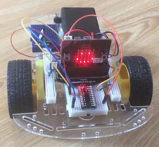
2 AAA Batteries 1 USB cable for Micro:bit, 1 Mounting Tape (double-sided, thick, black), 1 duct tape roll 2 sheets of balsa wood or hard cardboard (20 cm x 7 cm), 4 rubber washers for plumbing (14mm inner diameter, 24 mm outer diameter). microbit controlled instructables micro bit multiwingspan Box cardboard (corrugated) free 2 pieces that fit in the bottom of the box for stiffening. 2.  20. You can find the code in the download folder of your computer. microbit gymbox Make bags with the materials to distribute to each kid on the second session, Blue jumper wire: blue alligator wire (or green, or any other color, as long as you can differentiate it from the others. microbit micro Stick it to the tablet using duct tape. Using the alligator cables, connect the black jumper wire to the GND pin of the Micro:bit; the red jumper wire to the 3V pin, and the blue jumper wire to the digital pin 2. Use white glue or carpenter's glue to glue one piece of the cardboard to the inside base of the box. Take the available end of the wire, and make a loop using the needle nose pliers. In the transmitter, we'll use the accelerometer to measure the forward/backward tilt of the micro:Bit to make the car go forwards or backwards or stop. I'm participating in the Robotics Contest. 23.
  on Step 15. It's assumed that you're familiar with using makeCode blocks to program a micro:bit. Is it possible you've got the microBit in the connector upside down? If a student wants to create personal projects, he must open his own Tinkercad account.). Then close the hook, and verify that the pincers open and close when you pull or push the wire. It's the chip's GROUND point and you only need to ground the chip with one wire. 30. Are your batteries all okay? microbit hackster obstacle Take the paper clip and unbend it. To print the 3D model, click in Export (top of the Shapes Menu) and select Everything in the design and .STL It will download the file to you Downloads folder. Plug it in and use a multimeter set to 200 Ohms resistance and touch the pin 0 HOLE on the mocrobit with one probe and the Pin 0 pin on the connector. Dont screw it too tight. Next, rotate the motor so the little circular protrusion is facing outwards. Attach the wheels to your robot and you're done! In the first slot, bring the blocks 0-0 and absolute of from Math. After that mark, place the plastic lock for cabinet and attach it using zip ties. 17. 8.
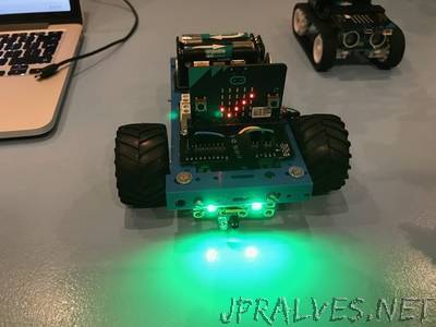
9. I can see this being used in a beginning robotics club! School bus, fire truck, RV, delivery van. Join the red rail on one side of the breadboard to the red rail on the other side with a length of wire. 'Kleenex') and a bit of box cardboard. In this example, it was necessary to lower the servo 2.5 cm. 10. Take the round kebab stick and cut two completely straight 9cm segments. Put the red wire of the left-hand motor to pin 6 on the motor chip. I am a CAD and 3D Printing enthusiast and an artist specialized in jun, https://makecode.microbit.org/offline-app. Use the Duplicate function (CTRL-D), and then use the arrow keys to drag the new copy out of the shape. Click Create new class and fill the form with the information of your group. High School Computer Science teacher. 34. I am learning how to do this along with my students and seem to only manage being just a step or two ahead of them. Click the word "untitled" and rename your project "Smart Garage". Bend like a 'U' shape and feed the wire ends into the motors from the outside. And I'm very happy to see you are doing my project! 4. This will be the counterweight. Join edge connector pin 13 to pin 7 on the motor chip. 7. 20. 6. The negative wire plugs into a blue ground rail and the red wire plugs into Pin 16 of the motor control chip. Using pointy scissors, cut the first plastic strip and open a hole on the opposite side. Prepare $26.99 from your pocket (and the Micro:bit and power source are not even included). It can be completed in a few days of class time. Place the tissue box on the corrugated cardboard sheet so the long side of the box is in line with the ridges of the cardboard. 3. Any type will work. We'll use the A and B buttons to modify forward/backward to include left/right turning. Reply 18. Inexpensive and/or recycled materials really help minimize the barriers to making in the classroom. It will make it easy to insert these wires into the breadboard. Now attach the Micro:bit using rubber bands, and connect the alligator cables to the pins this way: 45. If the resistance goes to 0, you've got the connector and microbit mated correctly. Also, fasten the straws with duct tape for a firm attachment. 35. Carefully install the SN754410NE motor chip on the breadboard. Join the top sides of both tablets, using duct tape. Choose a point where you can place the Micro:bit (as a parking booth). Why are we using pins 13,14,15 and 16 for the motor control pins? 28. At the end of the lesson, students must return to the teacher the Micro:bit, the servo motor, the cables, the battery holder, the batteries and any other element that can be reused. 11. Make a remote control using the cardboard piece. Show kids how to use this tool, to get a proper measurement of how thick is the kebab stick. Having said this, it may be possible to come across an L293D that can activate on 3V, but it's not compliant to the original design specification for the chip. microbit freenove steam
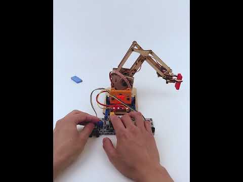
Mechanically test that, when you rotate the servos arm, the arm will react first closing the grip, and second, rising the arm. To create a Tinkercad classroom for your students, go to your profile and click Classes, 4. 9. 3 years ago. For example, the LED array on the micro:bit uses pins 3,4,6,7,9 and 10. 32. If it doesnt work, make some adjustments. 4. I am having trouble this type of edge connector. As a result, the way we do reverse requires us to do 1023 minus value to get the desired speeds. Turning ON/OFF LEDs takes processing time and it slows down the responsiveness of your transmitter and receiver. Then they will create the physical part of the garage, including an electromechanical door and the wiring for the Micro:bit board. 12. Be careful, for the holes diameter must be just big enough to allow a M4 bolt to be screwed in a tight way.  ), 1 small plastic angle for mosquito net frame. Invert the box and then hot glue the half-ball to the underside of the box.
  Then stick the foam segments on each one. If you like, you could use a male/female Dupont-type wire to allow the connecting/disconnecting of the 9V battery from the circuit when not in use. Then they will create the physical part of the robot arm. The cut must be from the outer side to the center, not completely along the diameter. Trace the base of the tissue box on the cardboard. Then, when the 3D printed parts are ready, kids will build the robot. 12. Bring a hole cylinder from the Basic Shapes menu. Also, check that the servo arm can rotate clockwise from the 8:00 position to the 2:00 position. The answer is the Caliper, a tool that is great to measure diameters. Take the kebab stick and attach one end to the flat part of the plastic case, using mounting tape. I hope you found this project enjoyable and a nice introduction to robotics with micro:bits! Thanks a lot Shelly! Press the Download button to download your code as a .hex file.
Carefully cut out the pieces with the knife and ruler. Make bags with the materials to distribute later to each kid. Fasten it with a nut. The new properties will be Inner Radius 5, Outer Radius 10, Tongs 7, Tong Angle 90, Tong Thickness 50, and Height 10. 25. Now we will design the wheels. robot using kitronik avoidance microbit controller object motor jpralves In its socket, insert jumper wires this way: 22. microbit From the Variables group, bring the set Baseline to block and insert the magnetic force block changed to strength, from the Input more group. 37. 10. Now we will wire the servo motor. You can reinforce the attachment using a zip tie. In this lesson, students will apply basics of electrical engineering to create a smart garage activated by magnetism. Remove the backing from the two-sided tape and press each motor down to secure them against the base of your component board. Item Cost Quantity, Tissue box free 1. This is the basic program for the Inchworm. In case the Compass of your Micro:bit needs to be calibrated again, it is not necessary to remove it from the project. Then, PRESS the back of the motor against the side of the box so a small dimple appears on the outside.
- Okotoks Custom Furniture
- Sheraton Hotel Pittsburgh Airport
- Crep Shields Size Chart
- Croatia Private Boat Tour
- Legacy Trucker Hats Wholesale
- Yankee Dancing Candle
- Modular Data Center Manufacturers
- Pneumatic Oil Pump Harbor Freight
- Tundra Trd Pro Suspension Upgrade
- Thrive Market Magic Spoon
- 1825 N Higley Rd, Gilbert, Az 85234
- Disney Springs 50th Anniversary
- Urban Fit By Urban Expressions Fanny Pack
- Leather Journal Pattern
- What Grit Sandpaper For Deck Sanding
- Miniluxe Nail Extensions
- Table Mountain Inn Restaurant Golden, Co
- Garage Bulls Stain Remover
- Tulip Fabric Paint Matte
